HP 17-p000 17-p199 - Maintenance and Service Guide - Page 53
Battery Board (select models only), Optical drive connector, Lift the battery board
 |
View all HP 17-p000 manuals
Add to My Manuals
Save this manual to your list of manuals |
Page 53 highlights
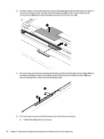
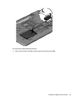
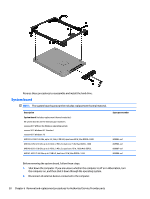
Battery Board (select models only) Description Battery board (with cable) Spare part number 763710-001 Before removing the battery board, follow these steps: 1. Disconnect all external devices connected to the computer. 2. Disconnect the power from the computer by first unplugging the power cord from the AC outlet and then unplugging the AC adapter from the computer. 3. Remove the battery (see Battery on page 26). 4. Remove the optical drive (see Optical drive on page 27). 5. Remove the base enclosure and top cover (see Base enclosure on page 30). Remove the battery board: 1. Turn the computer, with the front edge toward you. 2. Remove the two screws (1). 3. Lift the battery board (2) to remove it. Reverse this procedure to install the battery board. Optical drive connector NOTE: The optical drive connector and cable are included in the optical drive spare part kit. (See the Optical drive removal for more information for the spare part kit information.) Component replacement procedures 45
-
 1
1 -
2
-
3
-
4
-
5
-
6
-
7
-
8
-
9
-
10
-
11
-
12
-
13
-
14
-
15
-
16
-
17
-
18
-
19
-
20
-
21
-
22
-
23
-
24
-
25
-
26
-
27
-
28
-
29
-
30
-
31
-
32
-
33
-
34
-
35
-
36
-
37
-
38
-
39
-
40
-
41
-
42
-
43
-
44
-
45
-
46
-
47
-
 48
48 -
 49
49 -
 50
50 -
 51
51 -
 52
52 -
 53
53 -
 54
54 -
 55
55 -
 56
56 -
 57
57 -
 58
58 -
59
-
60
-
61
-
62
-
63
-
64
-
65
-
66
-
67
-
68
-
69
-
70
-
71
-
72
-
73
-
74
-
75
-
76
-
77
-
78
-
79
-
80
-
81
-
82
-
83
-
84
-
85
-
86
-
87
-
88
-
89
-
90
-
91
-
92
-
93
-
94
-
95
-
96
-
97
-
98
-
99
-
100
-
101
-
102
-
103
-
104
-
105
-
106
 |
 |
