HP 17-p000 17-p199 - Maintenance and Service Guide - Page 64
Power connector
 |
View all HP 17-p000 manuals
Add to My Manuals
Save this manual to your list of manuals |
Page 64 highlights
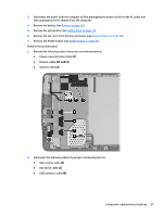
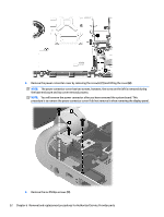
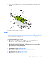
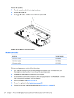
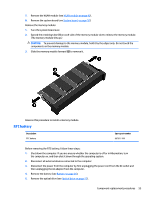
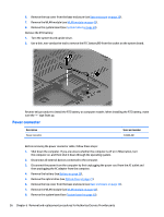
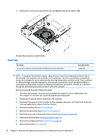
6. Remove the top cover from the base enclosure (see Base enclosure on page 30). 7. Remove the WLAN module (see WLAN module on page 42). 8. Remove the system board (see System board on page 50). Remove the RTC battery: 1. Turn the system board upside down. 2. Use a thin, non-conductive tool to remove the RTC battery (1) from the socket on the system board. Reverse this procedure to install the RTC battery on computer models. When installing the RTC battery, make sure the "+" sign faces up. Power connector Description Power connector Spare part number 763699-001 Before removing the power connector cable, follow these steps: 1. Shut down the computer. If you are unsure whether the computer is off or in Hibernation, turn the computer on, and then shut it down through the operating system. 2. Disconnect all external devices connected to the computer. 3. Disconnect the power from the computer by first unplugging the power cord from the AC outlet and then unplugging the AC adapter from the computer. 4. Remove the battery (see Battery on page 26), 5. Remove the optical drive (see Optical drive on page 27). 6. Remove the top cover from the base enclosure (see Base enclosure on page 30). 7. Remove the WLAN module (see WLAN module on page 42). 8. Remove the system board (see System board on page 50). 56 Chapter 6 Removal and replacement procedures for Authorized Service Provider parts
-
 1
1 -
2
-
3
-
4
-
5
-
6
-
7
-
8
-
9
-
10
-
11
-
12
-
13
-
14
-
15
-
16
-
17
-
18
-
19
-
20
-
21
-
22
-
23
-
24
-
25
-
26
-
27
-
28
-
29
-
30
-
31
-
32
-
33
-
34
-
35
-
36
-
37
-
38
-
39
-
40
-
41
-
42
-
43
-
44
-
45
-
46
-
47
-
48
-
49
-
50
-
51
-
52
-
53
-
54
-
55
-
56
-
57
-
58
-
 59
59 -
 60
60 -
 61
61 -
 62
62 -
 63
63 -
 64
64 -
 65
65 -
 66
66 -
 67
67 -
 68
68 -
 69
69 -
70
-
71
-
72
-
73
-
74
-
75
-
76
-
77
-
78
-
79
-
80
-
81
-
82
-
83
-
84
-
85
-
86
-
87
-
88
-
89
-
90
-
91
-
92
-
93
-
94
-
95
-
96
-
97
-
98
-
99
-
100
-
101
-
102
-
103
-
104
-
105
-
106
 |
 |
