HP 17-p000 17-p199 - Maintenance and Service Guide - Page 65
Fan, Remove the WLAN module see
 |
View all HP 17-p000 manuals
Add to My Manuals
Save this manual to your list of manuals |
Page 65 highlights
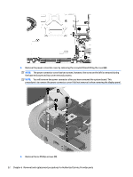
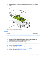
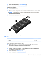
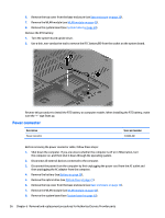
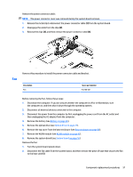
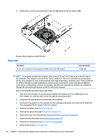
Remove the power connector cable: NOTE: The power connector cover was removed during the system board removal. 1. Release the metal clip to disconnect the power connector cable (1) from the system board. 2. Disengage the cable from the clips (2). 3. Release the clips (3), and then remove the power connector cable (4). Fan Reverse this procedure to install the power connector cable and bracket. Description Fan Spare part number 765788-001 Before removing the Fan, follow these steps: 1. Shut down the computer. If you are unsure whether the computer is off or in Hibernation, turn the computer on, and then shut it down through the operating system. 2. Disconnect all external devices connected to the computer. 3. Disconnect the power from the computer by first unplugging the power cord from the AC outlet and then unplugging the AC adapter from the computer. 4. Remove the battery (see Battery on page 26), 5. Remove the optical drive (see Optical drive on page 27). 6. Remove the top cover from the base enclosure (see Base enclosure on page 30). 7. Remove the WLAN module (see WLAN module on page 42). 8. Remove the system board (see System board on page 50). Remove the fan: 1. Turn the system board upside down. 2. Disconnect the fan cable from the system board, and then remove the piece of tape that secures the fan to the heat sink (1). Component replacement procedures 57
-
 1
1 -
2
-
3
-
4
-
5
-
6
-
7
-
8
-
9
-
10
-
11
-
12
-
13
-
14
-
15
-
16
-
17
-
18
-
19
-
20
-
21
-
22
-
23
-
24
-
25
-
26
-
27
-
28
-
29
-
30
-
31
-
32
-
33
-
34
-
35
-
36
-
37
-
38
-
39
-
40
-
41
-
42
-
43
-
44
-
45
-
46
-
47
-
48
-
49
-
50
-
51
-
52
-
53
-
54
-
55
-
56
-
57
-
58
-
59
-
 60
60 -
 61
61 -
 62
62 -
 63
63 -
 64
64 -
 65
65 -
 66
66 -
 67
67 -
 68
68 -
 69
69 -
 70
70 -
71
-
72
-
73
-
74
-
75
-
76
-
77
-
78
-
79
-
80
-
81
-
82
-
83
-
84
-
85
-
86
-
87
-
88
-
89
-
90
-
91
-
92
-
93
-
94
-
95
-
96
-
97
-
98
-
99
-
100
-
101
-
102
-
103
-
104
-
105
-
106
 |
 |
