HP 17-p000 17-p199 - Maintenance and Service Guide - Page 40
Turn the computer right side up and carefully remove the top cover., Use a thin
 |
View all HP 17-p000 manuals
Add to My Manuals
Save this manual to your list of manuals |
Page 40 highlights
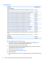
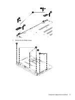
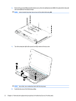
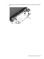
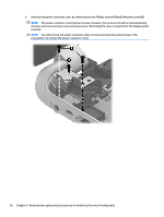
3. Remove five screws (1) around the battery area, three broadhead screws (2) in the optical drive bay and one screw (3) near the display hinge. NOTE: Some models may have two screws in the optical drive bay (2). 4. Turn the computer right side up and carefully remove the top cover. NOTE: Use a thin, non-conductive tool to lift the top cover. 5. Carefully disconnect the following cables: 32 Chapter 6 Removal and replacement procedures for Authorized Service Provider parts
-
 1
1 -
2
-
3
-
4
-
5
-
6
-
7
-
8
-
9
-
10
-
11
-
12
-
13
-
14
-
15
-
16
-
17
-
18
-
19
-
20
-
21
-
22
-
23
-
24
-
25
-
26
-
27
-
28
-
29
-
30
-
31
-
32
-
33
-
34
-
 35
35 -
 36
36 -
 37
37 -
 38
38 -
 39
39 -
 40
40 -
 41
41 -
 42
42 -
 43
43 -
 44
44 -
 45
45 -
46
-
47
-
48
-
49
-
50
-
51
-
52
-
53
-
54
-
55
-
56
-
57
-
58
-
59
-
60
-
61
-
62
-
63
-
64
-
65
-
66
-
67
-
68
-
69
-
70
-
71
-
72
-
73
-
74
-
75
-
76
-
77
-
78
-
79
-
80
-
81
-
82
-
83
-
84
-
85
-
86
-
87
-
88
-
89
-
90
-
91
-
92
-
93
-
94
-
95
-
96
-
97
-
98
-
99
-
100
-
101
-
102
-
103
-
104
-
105
-
106
 |
 |

3.
Remove five screws
(1)
around the battery area, three broadhead screws
(2)
in the optical drive bay and
one screw
(3)
near the display hinge.
NOTE:
Some models may have two screws in the optical drive bay
(2)
.
4.
Turn the computer right side up and carefully remove the top cover.
NOTE:
Use a thin, non-conductive tool to lift the top cover.
5.
Carefully disconnect the following cables:
32
Chapter 6
Removal and replacement procedures for Authorized Service Provider parts