HP 17-p000 17-p199 - Maintenance and Service Guide - Page 44
the base enclosure and top cover removal process. Removing the cover is required for the display panel
 |
View all HP 17-p000 manuals
Add to My Manuals
Save this manual to your list of manuals |
Page 44 highlights
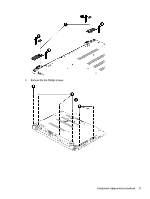
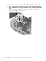
4. Remove the power connector cover by removing the two Phillips screws (1) and lifting the cover (2). NOTE: The power connector cover has two screws, however, the screw on the left is removed during the base enclosure and top cover removal process. Removing the cover is required for the display panel removal. NOTE: You will remove the power connector after you have removed the system board. This procedure is to remove the power connector cover. 36 Chapter 6 Removal and replacement procedures for Authorized Service Provider parts
-
 1
1 -
2
-
3
-
4
-
5
-
6
-
7
-
8
-
9
-
10
-
11
-
12
-
13
-
14
-
15
-
16
-
17
-
18
-
19
-
20
-
21
-
22
-
23
-
24
-
25
-
26
-
27
-
28
-
29
-
30
-
31
-
32
-
33
-
34
-
35
-
36
-
37
-
38
-
 39
39 -
 40
40 -
 41
41 -
 42
42 -
 43
43 -
 44
44 -
 45
45 -
 46
46 -
 47
47 -
 48
48 -
 49
49 -
50
-
51
-
52
-
53
-
54
-
55
-
56
-
57
-
58
-
59
-
60
-
61
-
62
-
63
-
64
-
65
-
66
-
67
-
68
-
69
-
70
-
71
-
72
-
73
-
74
-
75
-
76
-
77
-
78
-
79
-
80
-
81
-
82
-
83
-
84
-
85
-
86
-
87
-
88
-
89
-
90
-
91
-
92
-
93
-
94
-
95
-
96
-
97
-
98
-
99
-
100
-
101
-
102
-
103
-
104
-
105
-
106
 |
 |

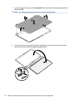
4.
Remove the power connector cover by removing the two Phillips screws
(1)
and lifting the cover
(2)
.
NOTE:
The power connector cover has two screws, however, the screw on the left is removed during
the base enclosure and top cover removal process. Removing the cover is required for the display panel
removal.
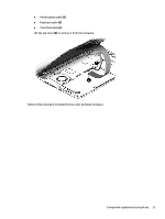
NOTE:
You will remove the power connector after you have removed the system board. This
procedure is to remove the power connector cover.
36
Chapter 6
Removal and replacement procedures for Authorized Service Provider parts