HP 17-p000 17-p199 - Maintenance and Service Guide - Page 48
Removal and replacement procedures for Authorized Service Provider parts
 |
View all HP 17-p000 manuals
Add to My Manuals
Save this manual to your list of manuals |
Page 48 highlights
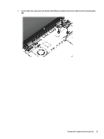
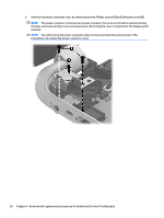
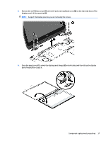
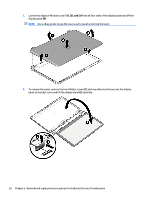
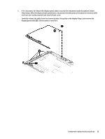
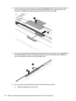
10. On select models, removing the panel also requires disengaging the panel from the back cover latch. To disconnect the display panel, carefully rotate the display panel (1) to open it. Push upward on the connection latch (2)panel and then disengage the panel from the back cover (3). 11. If it is necessary to replace the webcamera/microphone perform the following: Lift the module (1) from the adhesive holding it in place on the display bezel and disconnect the module connector (2) if you have not already done so when removing the display cable. 12. If it is necessary to replace the WLAN antenna cable, follow these procedures: a. Position the display back cover face up. 40 Chapter 6 Removal and replacement procedures for Authorized Service Provider parts
-
 1
1 -
2
-
3
-
4
-
5
-
6
-
7
-
8
-
9
-
10
-
11
-
12
-
13
-
14
-
15
-
16
-
17
-
18
-
19
-
20
-
21
-
22
-
23
-
24
-
25
-
26
-
27
-
28
-
29
-
30
-
31
-
32
-
33
-
34
-
35
-
36
-
37
-
38
-
39
-
40
-
41
-
42
-
 43
43 -
 44
44 -
 45
45 -
 46
46 -
 47
47 -
 48
48 -
 49
49 -
 50
50 -
 51
51 -
 52
52 -
 53
53 -
54
-
55
-
56
-
57
-
58
-
59
-
60
-
61
-
62
-
63
-
64
-
65
-
66
-
67
-
68
-
69
-
70
-
71
-
72
-
73
-
74
-
75
-
76
-
77
-
78
-
79
-
80
-
81
-
82
-
83
-
84
-
85
-
86
-
87
-
88
-
89
-
90
-
91
-
92
-
93
-
94
-
95
-
96
-
97
-
98
-
99
-
100
-
101
-
102
-
103
-
104
-
105
-
106
 |
 |
