HP 6120XG HP ProCurve Series 6120 Blade Switches Advanced Traffic Management G - Page 71
Example of Management VLAN Control in a LAN, Table 2-5. VLAN Membership
 |
View all HP 6120XG manuals
Add to My Manuals
Save this manual to your list of manuals |
Page 71 highlights
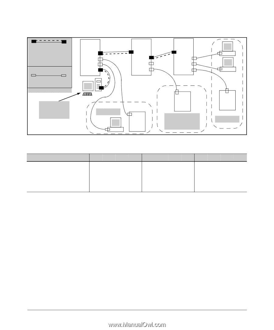
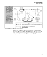
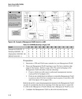
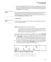
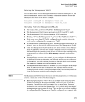
Static Virtual LANs (VLANs) Special VLAN Types Links with Ports Configured as Members of the Management VLAN and other VLANs Links Not Belonging to the Management VLAN Switch A Port A1 Port A3 Port A6 Port A7 1 Switch B Port B2 Port B4 Port B5 Port B9 System Management Workstation Shipping 2 Server Switch C Port C2 Port C3 Port C6 Port C8 Server System Server (on the DEFAULT_VLAN) 3 4 Server Marketing Figure 2-30. Example of Management VLAN Control in a LAN Table 2-5. VLAN Membership in Figure 2-30 Switch A1 A3 A6 A7 B2 B4 B5 B9 C2 C3 C6 C8 Management VLAN (VID = 7) YNNY Y YNNYNNN Marketing VLAN (VID = 12) NNNNNNNNNY Y Y Shipping Dept. VLAN (VID = 20) N Y Y N N N N N N N N N DEFAULT-VLAN (VID = 1) YYYYYYYYYYYY Preparation 1. Determine a VID and VLAN name suitable for your Management VLAN. 2. Plan your Management VLAN topology to use ProCurve switches that support this feature. (Refer to page 2-46.) The ports belonging to the Management VLAN should be only the following: • Ports to which you will connect authorized management stations (such as Port A7 in figure 2-30.) • Ports on one switch that you will use to extend the Management VLAN to ports on other ProCurve switches (such as ports A1 and B2 or B4 and C2 in figure 2-30 on page 2-48.). Hubs dedicated to connecting management stations to the Management VLAN can also be included in the above topology. Note that any device connected to a hub in the Management VLAN will also have Management VLAN access. 3. Configure the Management VLAN on the selected switch ports. 2-48
-
 1
1 -
2
-
3
-
4
-
5
-
6
-
7
-
8
-
9
-
10
-
11
-
12
-
13
-
14
-
15
-
16
-
17
-
18
-
19
-
20
-
21
-
22
-
23
-
24
-
25
-
26
-
27
-
28
-
29
-
30
-
31
-
32
-
33
-
34
-
35
-
36
-
37
-
38
-
39
-
40
-
41
-
42
-
43
-
44
-
45
-
46
-
47
-
48
-
49
-
50
-
51
-
52
-
53
-
54
-
55
-
56
-
57
-
58
-
59
-
60
-
61
-
62
-
63
-
64
-
65
-
 66
66 -
 67
67 -
 68
68 -
 69
69 -
 70
70 -
 71
71 -
 72
72 -
 73
73 -
 74
74 -
 75
75 -
 76
76 -
77
-
78
-
79
-
80
-
81
-
82
-
83
-
84
-
85
-
86
-
87
-
88
-
89
-
90
-
91
-
92
-
93
-
94
-
95
-
96
-
97
-
98
-
99
-
100
-
101
-
102
-
103
-
104
-
105
-
106
-
107
-
108
-
109
-
110
-
111
-
112
-
113
-
114
-
115
-
116
-
117
-
118
-
119
-
120
-
121
-
122
-
123
-
124
-
125
-
126
-
127
-
128
-
129
-
130
-
131
-
132
-
133
-
134
-
135
-
136
-
137
-
138
-
139
-
140
-
141
-
142
-
143
-
144
-
145
-
146
-
147
-
148
-
149
-
150
-
151
-
152
-
153
-
154
-
155
-
156
-
157
-
158
-
159
-
160
-
161
-
162
-
163
-
164
-
165
-
166
-
167
-
168
-
169
-
170
-
171
-
172
-
173
-
174
-
175
-
176
-
177
-
178
-
179
-
180
-
181
-
182
-
183
-
184
-
185
-
186
-
187
-
188
-
189
-
190
-
191
-
192
-
193
-
194
-
195
-
196
-
197
-
198
-
199
-
200
-
201
-
202
-
203
-
204
-
205
-
206
-
207
-
208
-
209
-
210
-
211
-
212
-
213
-
214
-
215
-
216
-
217
-
218
-
219
-
220
-
221
-
222
 |
 |