HP 6535b HP Compaq 6530b Notebook PC and HP Compaq 6535b Notebook PC - Mainten - Page 107
SIM connector board
 |
UPC - 884420171874
View all HP 6535b manuals
Add to My Manuals
Save this manual to your list of manuals |
Page 107 highlights
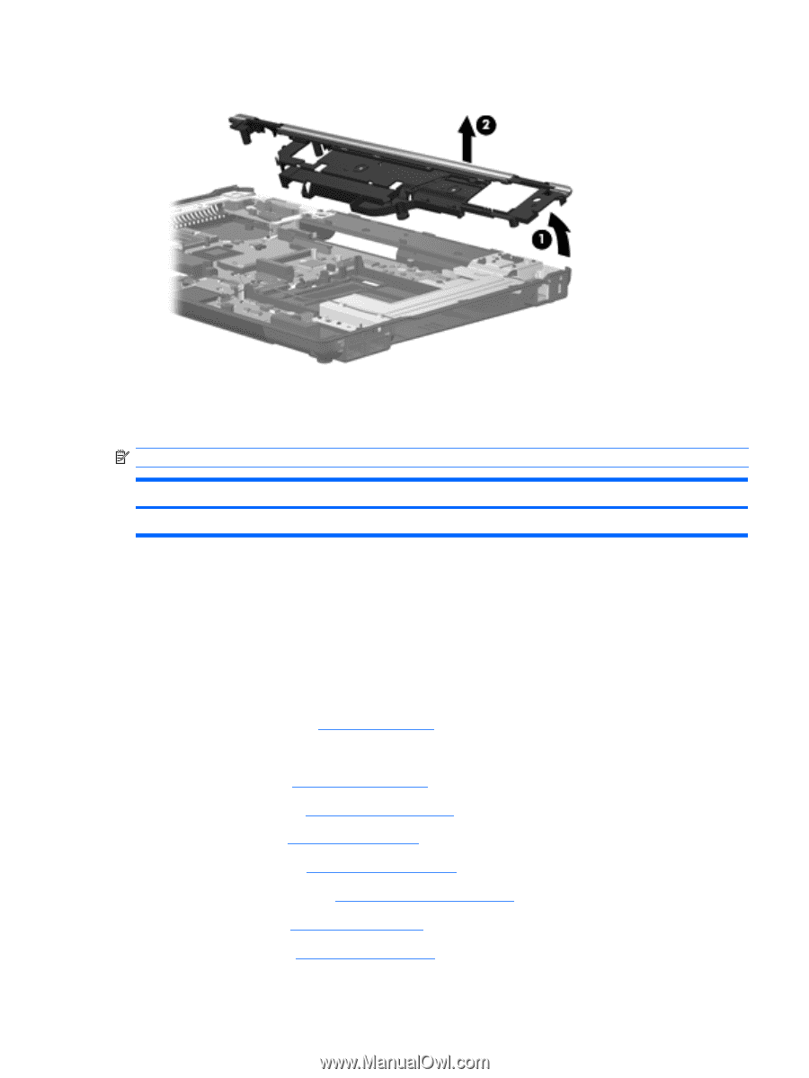
6. Remove the rear cover (2) by lifting it straight up. Reverse this procedure to install the rear cover. SIM connector board NOTE: This section applies only to computer models equipped with a WWAN module. Description SIM connector board Spare part number 486252-001 Before removing the SIM connector board, follow these steps: 1. Shut down the computer. If you are unsure whether the computer is off or in Hibernation, turn the computer on, and then shut it down through the operating system. 2. Disconnect all external devices connected to the computer. 3. Disconnect the power from the computer by first unplugging the power cord from the AC outlet and then unplugging the AC Adapter from the computer. 4. Remove the battery (see Battery on page 48). 5. Remove the following: a. Hard drive (see Hard drive on page 54) b. Optical drive (see Optical drive on page 57) c. Keyboard (see Keyboard on page 63) d. Switch cover (see Switch cover on page 67) e. Display assembly (see Display assembly on page 76) f. Top cover (see Top cover on page 83) g. Rear cover (see Rear cover on page 95) Component replacement procedures 97
-
 1
1 -
2
-
3
-
4
-
5
-
6
-
7
-
8
-
9
-
10
-
11
-
12
-
13
-
14
-
15
-
16
-
17
-
18
-
19
-
20
-
21
-
22
-
23
-
24
-
25
-
26
-
27
-
28
-
29
-
30
-
31
-
32
-
33
-
34
-
35
-
36
-
37
-
38
-
39
-
40
-
41
-
42
-
43
-
44
-
45
-
46
-
47
-
48
-
49
-
50
-
51
-
52
-
53
-
54
-
55
-
56
-
57
-
58
-
59
-
60
-
61
-
62
-
63
-
64
-
65
-
66
-
67
-
68
-
69
-
70
-
71
-
72
-
73
-
74
-
75
-
76
-
77
-
78
-
79
-
80
-
81
-
82
-
83
-
84
-
85
-
86
-
87
-
88
-
89
-
90
-
91
-
92
-
93
-
94
-
95
-
96
-
97
-
98
-
99
-
100
-
101
-
 102
102 -
 103
103 -
 104
104 -
 105
105 -
 106
106 -
 107
107 -
 108
108 -
 109
109 -
 110
110 -
 111
111 -
 112
112 -
113
-
114
-
115
-
116
-
117
-
118
-
119
-
120
-
121
-
122
-
123
-
124
-
125
-
126
-
127
-
128
-
129
-
130
-
131
-
132
-
133
-
134
-
135
-
136
-
137
-
138
-
139
-
140
-
141
-
142
-
143
-
144
-
145
-
146
-
147
-
148
-
149
-
150
-
151
-
152
-
153
-
154
-
155
-
156
-
157
-
158
-
159
-
160
-
161
-
162
-
163
-
164
-
165
-
166
-
167
-
168
-
169
-
170
-
171
-
172
-
173
-
174
-
175
-
176
-
177
-
178
-
179
 |
 |