HP 6535b HP Compaq 6530b Notebook PC and HP Compaq 6535b Notebook PC - Mainten - Page 113
Remove the Phillips PM2.0×5.0 screw, Remove the system board
 |
UPC - 884420171874
View all HP 6535b manuals
Add to My Manuals
Save this manual to your list of manuals |
Page 113 highlights
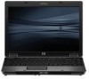
6. Remove the Phillips PM2.0×5.0 screw (3) that secures the system board to the base enclosure. 7. Use the optical drive connector (1) to lift the right side of the system board (2) until it rests at an angle. 8. Remove the system board (3) from the base enclosure by sliding it up and to the right. Reverse the preceding procedure to install the system board. Component replacement procedures 103
-
 1
1 -
2
-
3
-
4
-
5
-
6
-
7
-
8
-
9
-
10
-
11
-
12
-
13
-
14
-
15
-
16
-
17
-
18
-
19
-
20
-
21
-
22
-
23
-
24
-
25
-
26
-
27
-
28
-
29
-
30
-
31
-
32
-
33
-
34
-
35
-
36
-
37
-
38
-
39
-
40
-
41
-
42
-
43
-
44
-
45
-
46
-
47
-
48
-
49
-
50
-
51
-
52
-
53
-
54
-
55
-
56
-
57
-
58
-
59
-
60
-
61
-
62
-
63
-
64
-
65
-
66
-
67
-
68
-
69
-
70
-
71
-
72
-
73
-
74
-
75
-
76
-
77
-
78
-
79
-
80
-
81
-
82
-
83
-
84
-
85
-
86
-
87
-
88
-
89
-
90
-
91
-
92
-
93
-
94
-
95
-
96
-
97
-
98
-
99
-
100
-
101
-
102
-
103
-
104
-
105
-
106
-
107
-
 108
108 -
 109
109 -
 110
110 -
 111
111 -
 112
112 -
 113
113 -
 114
114 -
 115
115 -
 116
116 -
 117
117 -
 118
118 -
119
-
120
-
121
-
122
-
123
-
124
-
125
-
126
-
127
-
128
-
129
-
130
-
131
-
132
-
133
-
134
-
135
-
136
-
137
-
138
-
139
-
140
-
141
-
142
-
143
-
144
-
145
-
146
-
147
-
148
-
149
-
150
-
151
-
152
-
153
-
154
-
155
-
156
-
157
-
158
-
159
-
160
-
161
-
162
-
163
-
164
-
165
-
166
-
167
-
168
-
169
-
170
-
171
-
172
-
173
-
174
-
175
-
176
-
177
-
178
-
179
 |
 |

6.
Remove the Phillips PM2.0×5.0 screw
(3)
that secures the system board to the base enclosure.
7.
Use the optical drive connector
(1)
to lift the right side of the system board
(2)
until it rests at an
angle.
8.
Remove the system board
(3)
from the base enclosure by sliding it up and to the right.
Reverse the preceding procedure to install the system board.
Component replacement procedures
103