HP 6535b HP Compaq 6530b Notebook PC and HP Compaq 6535b Notebook PC - Mainten - Page 112
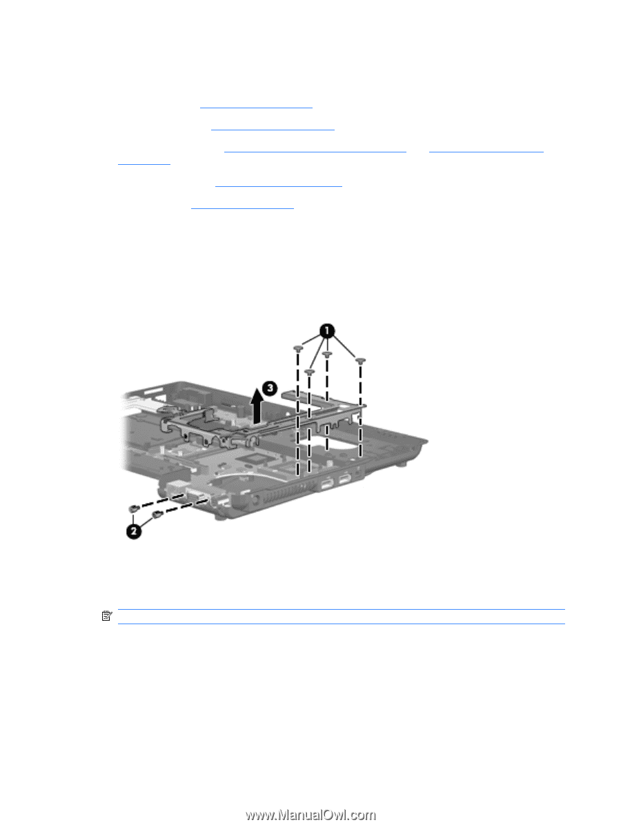
Position the computer with the front toward you., Remove the system board bracket
 |
UPC - 884420171874
View all HP 6535b manuals
Add to My Manuals
Save this manual to your list of manuals |
Page 112 highlights
When replacing the system board, be sure that the following components are removed from the defective system board and installed on the replacement system board: ● RTC battery (see RTC battery on page 56) ● WLAN module (see WLAN module on page 59) ● Memory modules (see Expansion memory module on page 61 and Primary memory module on page 65) ● WWAN module (see WWAN module on page 66) ● Processor (see Processor on page 74) Remove the system board: 1. Position the computer with rear panel toward you. 2. Remove the four Phillips PM2.0×3.0 broad-head screws (1) and the two hex HM5.0×9.0 screw locks (2) that secure the system board bracket to the base enclosure. 3. Remove the system board bracket (3). 4. Position the computer with the front toward you. 5. Disconnect the Bluetooth module cable (1) and the modem module cable (2) from the system board. NOTE: Step 6 applies only to computer models not equipped with WWAN capability. 102 Chapter 4 Removal and replacement procedures
-
 1
1 -
2
-
3
-
4
-
5
-
6
-
7
-
8
-
9
-
10
-
11
-
12
-
13
-
14
-
15
-
16
-
17
-
18
-
19
-
20
-
21
-
22
-
23
-
24
-
25
-
26
-
27
-
28
-
29
-
30
-
31
-
32
-
33
-
34
-
35
-
36
-
37
-
38
-
39
-
40
-
41
-
42
-
43
-
44
-
45
-
46
-
47
-
48
-
49
-
50
-
51
-
52
-
53
-
54
-
55
-
56
-
57
-
58
-
59
-
60
-
61
-
62
-
63
-
64
-
65
-
66
-
67
-
68
-
69
-
70
-
71
-
72
-
73
-
74
-
75
-
76
-
77
-
78
-
79
-
80
-
81
-
82
-
83
-
84
-
85
-
86
-
87
-
88
-
89
-
90
-
91
-
92
-
93
-
94
-
95
-
96
-
97
-
98
-
99
-
100
-
101
-
102
-
103
-
104
-
105
-
106
-
 107
107 -
 108
108 -
 109
109 -
 110
110 -
 111
111 -
 112
112 -
 113
113 -
 114
114 -
 115
115 -
 116
116 -
 117
117 -
118
-
119
-
120
-
121
-
122
-
123
-
124
-
125
-
126
-
127
-
128
-
129
-
130
-
131
-
132
-
133
-
134
-
135
-
136
-
137
-
138
-
139
-
140
-
141
-
142
-
143
-
144
-
145
-
146
-
147
-
148
-
149
-
150
-
151
-
152
-
153
-
154
-
155
-
156
-
157
-
158
-
159
-
160
-
161
-
162
-
163
-
164
-
165
-
166
-
167
-
168
-
169
-
170
-
171
-
172
-
173
-
174
-
175
-
176
-
177
-
178
-
179
 |
 |