HP EliteDesk 800 G8 Maintenance and Service Guide - Page 101
CAUTION, Patterns of blink/beep codes are determined by using the following parameters
 |
View all HP EliteDesk 800 G8 manuals
Add to My Manuals
Save this manual to your list of manuals |
Page 101 highlights
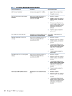
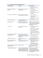
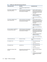
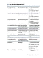
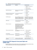
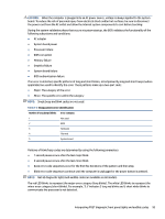
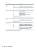
CAUTION: When the computer is plugged into an AC power source, voltage is always applied to the system board. To reduce the risk of personal injury from electrical shock and/or hot surfaces, be sure to disconnect the power cord from the AC outlet and allow the internal system components to cool before touching. During the system validation phase that occurs at system startup, the BIOS validates the functionality of the following subsystems and conditions: ● AC adapter ● System board power ● Processor failure ● BIOS corruption ● Memory failure ● Graphics failure ● System board failure ● BIOS authentication failure If an error is detected, specific patterns of long and short blinks, accompanied by long and short beeps (where applicable) are used to identify the error. These patterns make up a two-part code: ● Major: The category of the error ● Minor: The specific error within the category NOTE: Single beep and blink codes are not used. Table 7-2 Beep pattern error identification Number of long beeps/blinks Error category 1 Not used 2 BIOS 3 Hardware 4 Thermal 5 System board Patterns of blink/beep codes are determined by using the following parameters: ● 1 second pause occurs after the last major blink. ● 2 second pause occurs after the last minor blink. ● Beep error code sequences occur for the first five iterations of the pattern and then stop. ● Blink error code sequences continue until the computer is unplugged or the power button is pressed. NOTE: Not all diagnostic lights and audible codes are available on all models. The red LED blinks to represent the major error category (long blinks). The white LED blinks to represent the minor error category (short blinks). For example, '3.5' indicates 3 long red blinks and 5 short white blinks to communicate the processor is not detected. Interpreting POST diagnostic front panel lights and audible codes 93
-
 1
1 -
2
-
3
-
4
-
5
-
6
-
7
-
8
-
9
-
10
-
11
-
12
-
13
-
14
-
15
-
16
-
17
-
18
-
19
-
20
-
21
-
22
-
23
-
24
-
25
-
26
-
27
-
28
-
29
-
30
-
31
-
32
-
33
-
34
-
35
-
36
-
37
-
38
-
39
-
40
-
41
-
42
-
43
-
44
-
45
-
46
-
47
-
48
-
49
-
50
-
51
-
52
-
53
-
54
-
55
-
56
-
57
-
58
-
59
-
60
-
61
-
62
-
63
-
64
-
65
-
66
-
67
-
68
-
69
-
70
-
71
-
72
-
73
-
74
-
75
-
76
-
77
-
78
-
79
-
80
-
81
-
82
-
83
-
84
-
85
-
86
-
87
-
88
-
89
-
90
-
91
-
92
-
93
-
94
-
95
-
 96
96 -
 97
97 -
 98
98 -
 99
99 -
 100
100 -
 101
101 -
 102
102 -
 103
103 -
 104
104 -
 105
105 -
 106
106 -
107
-
108
-
109
-
110
-
111
-
112
-
113
-
114
-
115
-
116
-
117
-
118
-
119
-
120
-
121
-
122
-
123
-
124
-
125
 |
 |
