HP LH4r HP Netserver Service Handbook, Volume 2 - Mid - Page 11
System Board Connectors, Switches, and Jumpers
 |
View all HP LH4r manuals
Add to My Manuals
Save this manual to your list of manuals |
Page 11 highlights
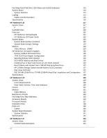
Power P1 & P2 Power Supply On Flexible disk drive cable connector IDE disk drive cable connector Internal SCSI connector Power P3 & P4 Main fan connector Slot 3 - PCI Slot 2 - PCI Slot 5 - EISA/ISA Control panel cable connector Battery connector Power Adapter (HP Remote Assistant) Pin 1 ROM Mounting pin SW1 system board switches Processor Board Hard disk activity light Slot 1 - EISA/ISA System Board System Board Connectors, Switches, and Jumpers The table below explains the system board markings for all connectors. Connector IDE disk drive cable Keyboard (bottom) Video Serial SCSI port B Number J9 J4 J10 J8 J13 Connector Flexible disk drive Mouse (top) Parallel SCSI port A EISA/ISA slots PCI slots Power supply Battery Processor board slot Power supply on Extra fan (not used) J17, J18 J2 (P1, P2) J12 (P3, P4) J5 J15 J3 J23 Fan Remote power supply Front panel ROM Hard disk activity light Not used Number J6 J4 J10 J11 J19, J20, J21, J22, J24 J14 J7 J1 U23 J16 J23 3
-
 1
1 -
2
-
3
-
4
-
5
-
 6
6 -
 7
7 -
 8
8 -
 9
9 -
 10
10 -
 11
11 -
 12
12 -
 13
13 -
 14
14 -
 15
15 -
 16
16 -
17
-
18
-
19
-
20
-
21
-
22
-
23
-
24
-
25
-
26
-
27
-
28
-
29
-
30
-
31
-
32
-
33
-
34
-
35
-
36
-
37
-
38
-
39
-
40
-
41
-
42
-
43
-
44
-
45
-
46
-
47
-
48
-
49
-
50
-
51
-
52
-
53
-
54
-
55
-
56
-
57
-
58
-
59
-
60
-
61
-
62
-
63
-
64
-
65
-
66
-
67
-
68
-
69
-
70
-
71
-
72
-
73
-
74
-
75
-
76
-
77
-
78
-
79
-
80
-
81
-
82
-
83
-
84
-
85
-
86
-
87
-
88
-
89
-
90
-
91
-
92
-
93
-
94
-
95
-
96
-
97
-
98
-
99
-
100
-
101
-
102
-
103
-
104
-
105
-
106
-
107
-
108
-
109
-
110
-
111
-
112
-
113
-
114
-
115
-
116
-
117
-
118
-
119
-
120
-
121
-
122
-
123
-
124
-
125
-
126
-
127
-
128
-
129
-
130
-
131
-
132
-
133
-
134
-
135
-
136
-
137
-
138
-
139
-
140
-
141
-
142
-
143
-
144
-
145
-
146
-
147
-
148
-
149
-
150
-
151
-
152
-
153
-
154
-
155
-
156
-
157
-
158
-
159
-
160
-
161
-
162
-
163
-
164
-
165
-
166
-
167
-
168
-
169
-
170
-
171
-
172
-
173
-
174
-
175
-
176
-
177
-
178
 |
 |
