HP LH4r HP Netserver Service Handbook, Volume 2 - Mid - Page 135
Boot Problem with Greater than 2 GB HP Disk Array Boot Drive
 |
View all HP LH4r manuals
Add to My Manuals
Save this manual to your list of manuals |
Page 135 highlights
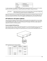
If more than three drives are installed, remove the Delayed Spin-Up jumper on drives with addresses 3, 4, 5, and 6. To find the Delayed Spin-Up jumper, orient the drive so the circuit board is on top and the power/SCSI connector is facing away from you. The jumper block is two-thirds of the way up the right edge of the circuit board. The jumper is in position 2 from the front of the drive and is labeled "DS" (refer to the "Technical Information" section in the hard disk Installation Guide). The result of this procedure is that several drives will spin up simultaneously. This may draw more current than the power supply can provide. If the system crashes due to a power supply failure, replace the jumpers and command the NOS to wait until the drives are initialized before initializing the network. The spin-up delay is the SCSI address multiplied by 15 seconds. This means that the drive at SCSI address 5 delays 75 seconds (5 x 15 seconds) before initializing. The NOS must wait at least as long as the drive with the longest delay so that it can recognize the drives. You may also reboot (push the reset button) after a Power On if the system completed its boot sequence before the last drive has spun up. Boot Problem with Greater than 2 GB HP Disk Array Boot Drive An array with total capacity greater than 2 GB, such as 3 or 4 drives, may have a boot error while booting the system. This is a BIOS limitation and can occur with any NOS or OS. If you have more than 2 GB total capacity, you must make the first logical partition less than or equal to 2 GB. Create the other partitions with the remaining capacity. Use the DOS utility for the Disk Array called JETSET.EXE. For example, if you are loading NetWare, which needs to first boot to DOS, create a small DOS partition (for example, 50 MB) for the first partition in JetSet and then create a second large partition with the remaining capacity. HP C2260A Storage System and the Built-in SCSI Connector The server has a built-in SCSI connector (in the back of the unit) which is a Fast SCSI-2 port. The HP C2260A Storage System is not compatible with Fast SCSI-2, and has not been supported on this SCSI connector. To connect an HP Storage System to the embedded Fast SCSI-2 subsystem, use the HP Fast SCSI-2 Kit (C3607A). The kit contains an active terminator, driver software, and installation instructions to support the HP Storage System on the embedded Fast SCSI-2 subsystem. Disk Array Controller Use the EISA Array Controller Card shipped with the Disk Array. This card provides the data protection and hot-spare capabilities of the HP Disk Array. Do not use the Disk Array storage cabinet with any other controller cards, including the controller integrated server. IDE 240 MB (D1697A) or 270 MB (D2894A) Hard Disk Installation and Configuration If you are installing one or two HP D1697A 240 MB IDE or HP D2894A 270 MB IDE hard disk drives using the IDE hard disk drive cable (P/N 5182-0016), follow these steps: 1.Connect the first (or only) hard disk to the connector labeled "PRIMARY" on the IDE hard disk drive cable. 2.Configure the primary drive to be the master drive by moving the IDE disk drive jumper from the CS position to the DS (master) position. The master drive is usually the first drive, but either drive can be the master. 3.Connect the second disk drive to the connector labeled "SECONDARY" on the IDE hard disk drive cable (P/N 5182-0016) and remove the jumper completely. 127
-
 1
1 -
2
-
3
-
4
-
5
-
6
-
7
-
8
-
9
-
10
-
11
-
12
-
13
-
14
-
15
-
16
-
17
-
18
-
19
-
20
-
21
-
22
-
23
-
24
-
25
-
26
-
27
-
28
-
29
-
30
-
31
-
32
-
33
-
34
-
35
-
36
-
37
-
38
-
39
-
40
-
41
-
42
-
43
-
44
-
45
-
46
-
47
-
48
-
49
-
50
-
51
-
52
-
53
-
54
-
55
-
56
-
57
-
58
-
59
-
60
-
61
-
62
-
63
-
64
-
65
-
66
-
67
-
68
-
69
-
70
-
71
-
72
-
73
-
74
-
75
-
76
-
77
-
78
-
79
-
80
-
81
-
82
-
83
-
84
-
85
-
86
-
87
-
88
-
89
-
90
-
91
-
92
-
93
-
94
-
95
-
96
-
97
-
98
-
99
-
100
-
101
-
102
-
103
-
104
-
105
-
106
-
107
-
108
-
109
-
110
-
111
-
112
-
113
-
114
-
115
-
116
-
117
-
118
-
119
-
120
-
121
-
122
-
123
-
124
-
125
-
126
-
127
-
128
-
129
-
 130
130 -
 131
131 -
 132
132 -
 133
133 -
 134
134 -
 135
135 -
 136
136 -
 137
137 -
 138
138 -
 139
139 -
 140
140 -
141
-
142
-
143
-
144
-
145
-
146
-
147
-
148
-
149
-
150
-
151
-
152
-
153
-
154
-
155
-
156
-
157
-
158
-
159
-
160
-
161
-
162
-
163
-
164
-
165
-
166
-
167
-
168
-
169
-
170
-
171
-
172
-
173
-
174
-
175
-
176
-
177
-
178
 |
 |
