HP OMEN 15.6 Maintenance and Service Guide - Page 42
Solid-state drive, To remove the solid-state drive, use this procedure and illustration.
 |
View all HP OMEN 15.6 manuals
Add to My Manuals
Save this manual to your list of manuals |
Page 42 highlights
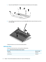
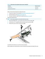
1. Remove the eight Phillips M2.0 × 6.0 screws that secure the bottom cover to the computer.. 2. Use a tool (1) to release the bottom cover near the display (2), and then remove the bottom cover from the computer (3). To replace the bottom cover, reverse the removal procedures. Solid-state drive To remove the solid-state drive, use this procedure and illustration. Table 5-2 Solid-state drive descriptions and part numbers Description 1 TB, PCIe, TLC 512 GB, PCIe, TLC 32 Chapter 5 Removal and replacement procedures for Customer Self-Repair parts Spare part number L85348-001 L85360-001
-
 1
1 -
2
-
3
-
4
-
5
-
6
-
7
-
8
-
9
-
10
-
11
-
12
-
13
-
14
-
15
-
16
-
17
-
18
-
19
-
20
-
21
-
22
-
23
-
24
-
25
-
26
-
27
-
28
-
29
-
30
-
31
-
32
-
33
-
34
-
35
-
36
-
 37
37 -
 38
38 -
 39
39 -
 40
40 -
 41
41 -
 42
42 -
 43
43 -
 44
44 -
 45
45 -
 46
46 -
 47
47 -
48
-
49
-
50
-
51
-
52
-
53
-
54
-
55
-
56
-
57
-
58
-
59
-
60
-
61
-
62
-
63
-
64
-
65
-
66
-
67
-
68
-
69
-
70
-
71
-
72
-
73
-
74
-
75
-
76
-
77
-
78
-
79
-
80
-
81
-
82
-
83
-
84
-
85
-
86
-
87
-
88
-
89
-
90
-
91
-
92
-
93
-
94
-
95
-
96
-
97
-
98
 |
 |
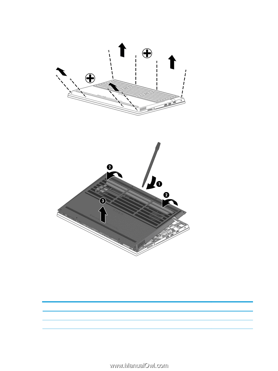
1.
Remove the eight Phillips M2.0 × 6.0 screws that secure the bottom cover to the computer..
2.
Use a tool
(1)
to release the bottom cover near the display
(2)
, and then remove the bottom cover from
the computer
(3)
.
To replace the bottom cover, reverse the removal procedures.
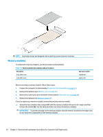
Solid-state drive
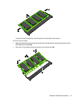
To remove the solid-state drive, use this procedure and illustration.
Table 5-2
Solid-state drive descriptions and part numbers
Description
Spare part number
1 TB, PCIe, TLC
L85348-001
512 GB, PCIe, TLC
L85360-001
32
Chapter 5
Removal and replacement procedures for Customer Self-Repair parts