HP OMEN 15.6 Maintenance and Service Guide - Page 59
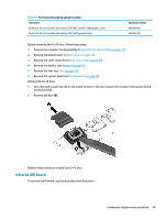
Infrared (IR) board, to release
 |
View all HP OMEN 15.6 manuals
Add to My Manuals
Save this manual to your list of manuals |
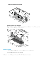
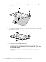
Page 59 highlights
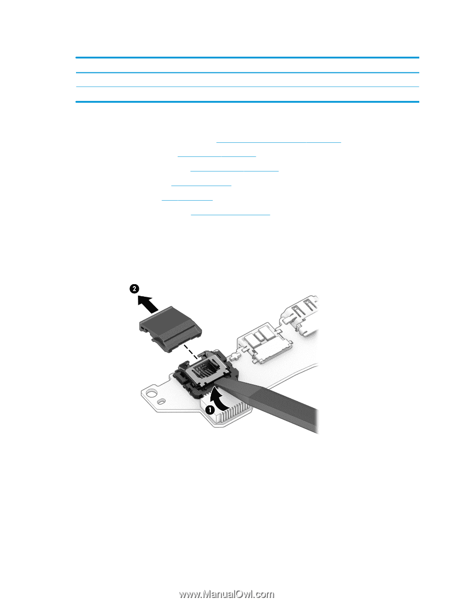
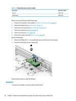
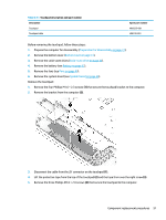
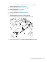
Table 6-9 RJ-45 door description and part number Description RJ-45 door for use in models with GeForce GTX 1660Ti and RTX 2060 graphics cards RJ-45 door for use in models with GeForce GTX 1650Ti graphics cards Spare part number M00636-001 M00637-001 Before removing the RJ-45 door, follow these steps: 1. Prepare the computer for disassembly (Preparation for disassembly on page 31). 2. Remove the bottom cover (Bottom cover on page 31). 3. Remove the solid-state drives (Solid-state drive on page 32). 4. Remove the battery (see Battery on page 37). 5. Remove the fans (see Fans on page 44). 6. Remove the system board (see System board on page 46). Remove the RJ-45 door: 1. Use a flat tool to push the tab on the inside-bottom of the door toward the outside of the system board to release it (1). 2. Remove the door (2). Reverse this procedure to install the RJ-45 door. Infrared (IR) board To remove the IR board, use this procedure and illustration. Component replacement procedures 49
-
 1
1 -
2
-
3
-
4
-
5
-
6
-
7
-
8
-
9
-
10
-
11
-
12
-
13
-
14
-
15
-
16
-
17
-
18
-
19
-
20
-
21
-
22
-
23
-
24
-
25
-
26
-
27
-
28
-
29
-
30
-
31
-
32
-
33
-
34
-
35
-
36
-
37
-
38
-
39
-
40
-
41
-
42
-
43
-
44
-
45
-
46
-
47
-
48
-
49
-
50
-
51
-
52
-
53
-
 54
54 -
 55
55 -
 56
56 -
 57
57 -
 58
58 -
 59
59 -
 60
60 -
 61
61 -
 62
62 -
 63
63 -
 64
64 -
65
-
66
-
67
-
68
-
69
-
70
-
71
-
72
-
73
-
74
-
75
-
76
-
77
-
78
-
79
-
80
-
81
-
82
-
83
-
84
-
85
-
86
-
87
-
88
-
89
-
90
-
91
-
92
-
93
-
94
-
95
-
96
-
97
-
98
 |
 |