HP ProBook 4446s HP ProBook 4445s Notebook PC HP ProBook 4446s Notebook PC - M - Page 66
USB Module, Lift the two boards
 |
View all HP ProBook 4446s manuals
Add to My Manuals
Save this manual to your list of manuals |
Page 66 highlights
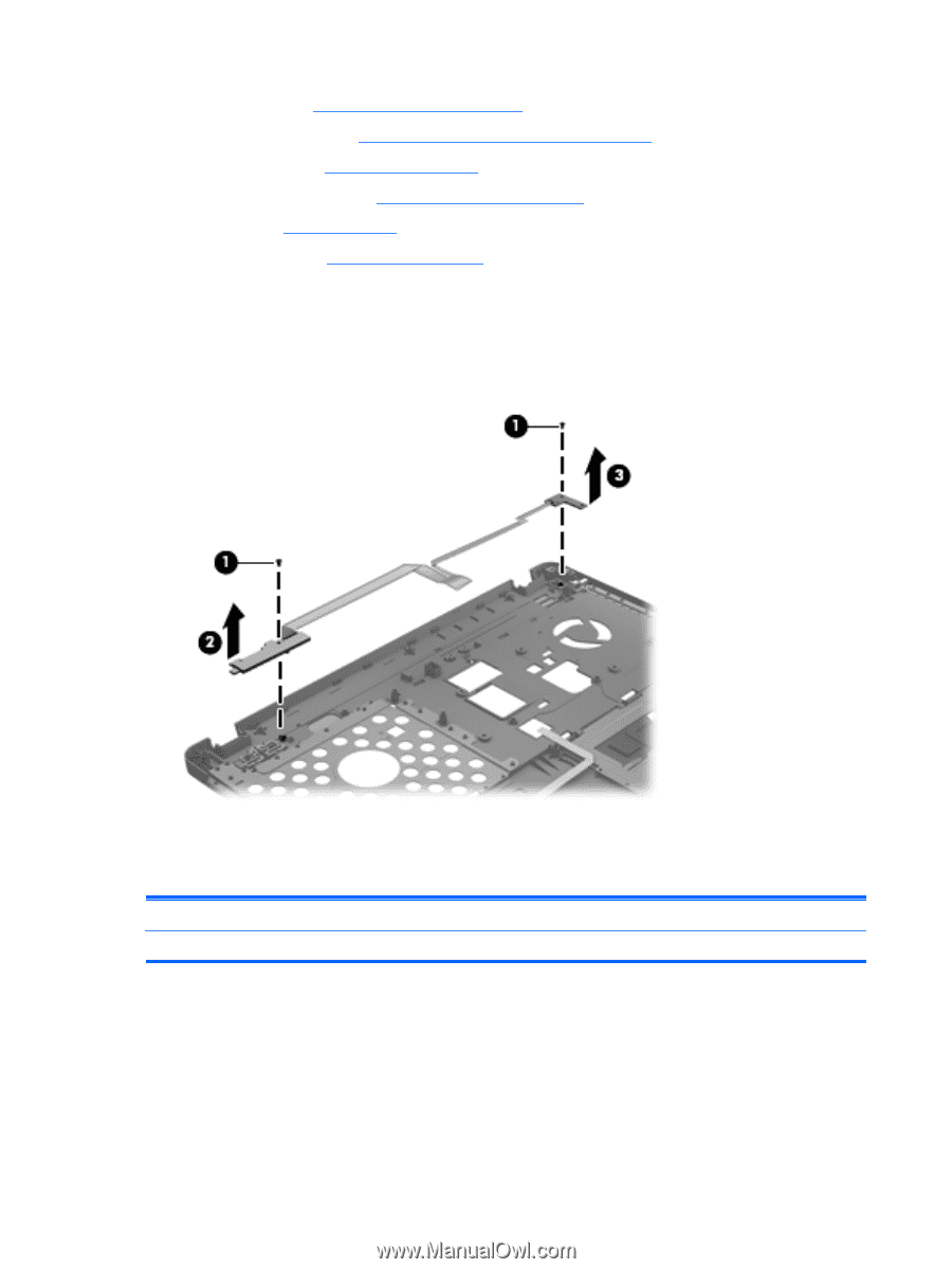
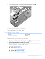
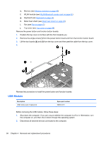
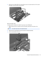
e. Memory (see Memory modules on page 40) f. WLAN module (see WLAN/Bluetooth combo card on page 42) g. Keyboard (see Keyboard on page 44) h. Metal heat shield (see Metal heat shield on page 46) i. Fan (see Fan on page 47) j. Top cover (see Top cover on page 48) Remove the power button and function button boards. 1. Position the top cover on its face with the front towards you. 2. Remove the single screw (1) from the power button board and from the function button board. 3. Lift the two boards (2) and (3) from the top cover and then peel the cable from the top cover. 4. Reverse this procedure to install the power button and function boards. USB Module Description USB module (part of spares kit) Spare part number 683640-001 Before removing the USB module, follow these steps: 1. Shut down the computer. If you are unsure whether the computer is off or in Hibernation, turn the computer on, and then shut it down through the operating system. 2. Disconnect all external devices connected to the computer. 58 Chapter 4 Removal and replacement procedures
-
 1
1 -
2
-
3
-
4
-
5
-
6
-
7
-
8
-
9
-
10
-
11
-
12
-
13
-
14
-
15
-
16
-
17
-
18
-
19
-
20
-
21
-
22
-
23
-
24
-
25
-
26
-
27
-
28
-
29
-
30
-
31
-
32
-
33
-
34
-
35
-
36
-
37
-
38
-
39
-
40
-
41
-
42
-
43
-
44
-
45
-
46
-
47
-
48
-
49
-
50
-
51
-
52
-
53
-
54
-
55
-
56
-
57
-
58
-
59
-
60
-
 61
61 -
 62
62 -
 63
63 -
 64
64 -
 65
65 -
 66
66 -
 67
67 -
 68
68 -
 69
69 -
 70
70 -
 71
71 -
72
-
73
-
74
-
75
-
76
-
77
-
78
-
79
-
80
-
81
-
82
-
83
-
84
-
85
-
86
-
87
-
88
-
89
-
90
-
91
-
92
-
93
-
94
-
95
-
96
-
97
-
98
-
99
-
100
-
101
-
102
-
103
-
104
-
105
-
106
-
107
-
108
-
109
-
110
-
111
-
112
-
113
-
114
 |
 |