HP ProBook 4446s HP ProBook 4445s Notebook PC HP ProBook 4446s Notebook PC - M - Page 67
from the system board., Disconnect the USB cable
 |
View all HP ProBook 4446s manuals
Add to My Manuals
Save this manual to your list of manuals |
Page 67 highlights
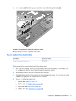
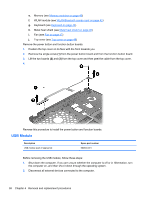
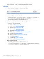
3. Disconnect the power from the computer by first unplugging the power cord from the AC outlet, and then unplugging the AC adapter from the computer. 4. Remove the following components: a. Battery (see Battery on page 33). b. Bottom door (see Bottom door on page 34). c. Hard drive (see Hard drive on page 38) d. Optical drive (see Optical drive on page 35) e. Memory (see Memory modules on page 40) f. WLAN module (see WLAN/Bluetooth combo card on page 42) g. Keyboard (see Keyboard on page 44) h. Metal heat shield (see Metal heat shield on page 46) i. Fan (see Fan on page 47) j. Top cover (see Top cover on page 48) Remove the USB module. 1. Position the top cover in the normal upright position with the lid in the open position. 2. Disconnect the USB cable (1) from the system board. 3. Remove the cable (2) from the base enclosure. 4. Remove the 2 screws (3) that secure the USB module. 5. Lift the module (4) from the system board. Reverse this procedure to install the USB module. Component replacement procedures 59
-
 1
1 -
2
-
3
-
4
-
5
-
6
-
7
-
8
-
9
-
10
-
11
-
12
-
13
-
14
-
15
-
16
-
17
-
18
-
19
-
20
-
21
-
22
-
23
-
24
-
25
-
26
-
27
-
28
-
29
-
30
-
31
-
32
-
33
-
34
-
35
-
36
-
37
-
38
-
39
-
40
-
41
-
42
-
43
-
44
-
45
-
46
-
47
-
48
-
49
-
50
-
51
-
52
-
53
-
54
-
55
-
56
-
57
-
58
-
59
-
60
-
61
-
 62
62 -
 63
63 -
 64
64 -
 65
65 -
 66
66 -
 67
67 -
 68
68 -
 69
69 -
 70
70 -
 71
71 -
 72
72 -
73
-
74
-
75
-
76
-
77
-
78
-
79
-
80
-
81
-
82
-
83
-
84
-
85
-
86
-
87
-
88
-
89
-
90
-
91
-
92
-
93
-
94
-
95
-
96
-
97
-
98
-
99
-
100
-
101
-
102
-
103
-
104
-
105
-
106
-
107
-
108
-
109
-
110
-
111
-
112
-
113
-
114
 |
 |