HP ProBook 4446s HP ProBook 4445s Notebook PC HP ProBook 4446s Notebook PC - M - Page 81
Remove the two Torx T8M2.5×6.0 screws, With the unit upside-down, remove the WLAN cables
 |
View all HP ProBook 4446s manuals
Add to My Manuals
Save this manual to your list of manuals |
Page 81 highlights
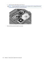
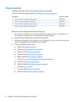
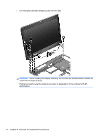
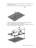
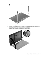
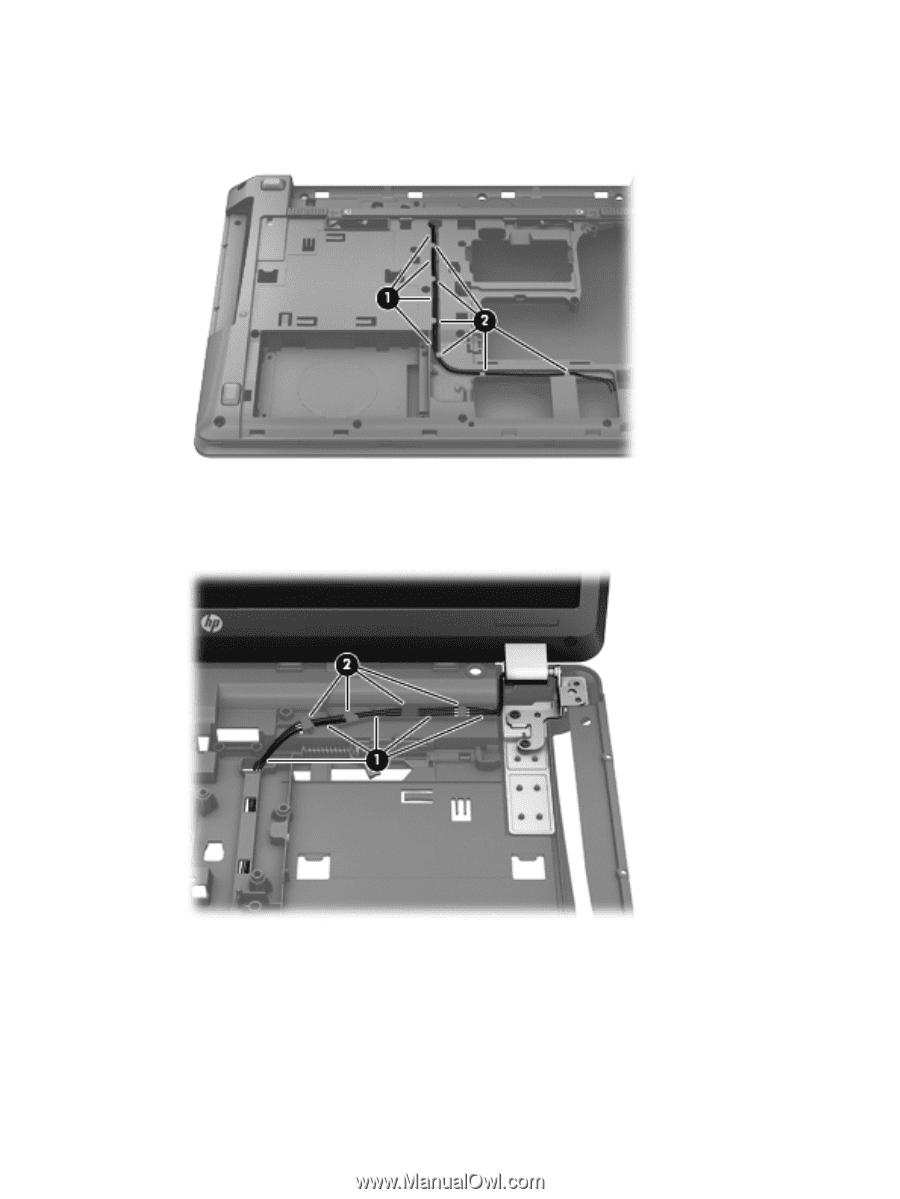
Remove the display assembly: 1. With the unit upside-down, remove the WLAN cables (1) from the raceway and the cable retainers (2). 2. Position the computer upright with the front toward you. 3. Open the computer as far as possible. 4. Remove the WLAN wires from the cable run (1) and the cable clips (2). 5. Remove the two Torx T8M2.5×6.0 screws (1) that secure the security bracket to the computer, and then lift the security bracket from the computer (2). 6. Remove the two Torx T8M2.5×6.0 screws (3) from the left hinge and the two Torx T8M2.5×6.0 screws (4) from the right hinge. Component replacement procedures 73
-
 1
1 -
2
-
3
-
4
-
5
-
6
-
7
-
8
-
9
-
10
-
11
-
12
-
13
-
14
-
15
-
16
-
17
-
18
-
19
-
20
-
21
-
22
-
23
-
24
-
25
-
26
-
27
-
28
-
29
-
30
-
31
-
32
-
33
-
34
-
35
-
36
-
37
-
38
-
39
-
40
-
41
-
42
-
43
-
44
-
45
-
46
-
47
-
48
-
49
-
50
-
51
-
52
-
53
-
54
-
55
-
56
-
57
-
58
-
59
-
60
-
61
-
62
-
63
-
64
-
65
-
66
-
67
-
68
-
69
-
70
-
71
-
72
-
73
-
74
-
75
-
 76
76 -
 77
77 -
 78
78 -
 79
79 -
 80
80 -
 81
81 -
 82
82 -
 83
83 -
 84
84 -
 85
85 -
 86
86 -
87
-
88
-
89
-
90
-
91
-
92
-
93
-
94
-
95
-
96
-
97
-
98
-
99
-
100
-
101
-
102
-
103
-
104
-
105
-
106
-
107
-
108
-
109
-
110
-
111
-
112
-
113
-
114
 |
 |
Remove the display assembly:
1.
With the unit upside-down, remove the WLAN cables
(1)
from the raceway and the cable
retainers
(2)
.
2.
Position the computer upright with the front toward you.
3.
Open the computer as far as possible.
4.
Remove the WLAN wires from the cable run
(1)
and the cable clips
(2)
.
5.
Remove the two Torx T8M2.5×6.0 screws
(1)
that secure the security bracket to the computer,
and then lift the security bracket from the computer
(2)
.
6.
Remove the two Torx T8M2.5×6.0 screws
(3)
from the left hinge and the two Torx T8M2.5×6.0
screws
(4)
from the right hinge.
Component replacement procedures
73