HP StorageWorks 2/64 HP StorageWorks Core Switch 2/64 and SAN Director 2/128 I - Page 89
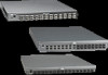
Cable management tray, Position and tighten the two attaching screws.
 |
View all HP StorageWorks 2/64 manuals
Add to My Manuals
Save this manual to your list of manuals |
Page 89 highlights
2. Install the new cable management tray: a. Orient tray as displayed in Figure 21 and insert the two tabs beneath the tray into the two slots at the bottom of the AC panel; then, rotate the front of the tray upward until it locks into place. b. Position and tighten the two attaching screws. c. Arrange the cables through or along the tray, as required. scale:.13865" = 1" SilkWorm 24000 Chassis 10 9 8 7 6 5 ! 4 15 d 3 ! 15 14 c d 2 1 ! 15 d 14 c 13 b 12 a 11 d 10 c 9 b 8 a 7 d 6 c ! ! RS - 232 RS - 232 IOIOI IOIOI 1Li0n/k100 Mb/s Active CP 1Li0n/k100 Mb/s Active CP ! 15 d 14 c 13 b 12 a 11 d 10 c 9 b 8 a 7 d 6 c 5 b 4 a 3 d 2 ! 15 d 14 c 13 b 12 a 11 d 10 c 9 b 8 a 7 d 6 c 5 b 4 a 3 d 2 c 1 14 13 c b 13 12 a b 12 11 a d 11 d 10 c 10 9 c b 9 8 a b 8 7 a d 7 d 6 c 6 5 c b 5 4 a b 4 3 a d 3 d 2 c 2 1 c b 1 0 a b 0 a 5 c b b 1 0 4 a b a 0 3 a d 2 c 1 b 0 a POWER SUPPLY 1 & 3 200-240 VAC 12A 50-60 Hz POWER SUPPLY 2 & 4 200-240 VAC 12A 50-60 Hz POWER SUPPLY 4 POWER SUPPLY 3 ! ! POWER SUPPLY 2 ! ! POWER SUPPLY 11 Cable Management Tray Attaching Screw (2x) Ground Strap Connector Figure 21 Cable management tray 2.026 Core Switch 2/64 and SAN Director 2/128 installation guide 89
-
 1
1 -
2
-
3
-
4
-
5
-
6
-
7
-
8
-
9
-
10
-
11
-
12
-
13
-
14
-
15
-
16
-
17
-
18
-
19
-
20
-
21
-
22
-
23
-
24
-
25
-
26
-
27
-
28
-
29
-
30
-
31
-
32
-
33
-
34
-
35
-
36
-
37
-
38
-
39
-
40
-
41
-
42
-
43
-
44
-
45
-
46
-
47
-
48
-
49
-
50
-
51
-
52
-
53
-
54
-
55
-
56
-
57
-
58
-
59
-
60
-
61
-
62
-
63
-
64
-
65
-
66
-
67
-
68
-
69
-
70
-
71
-
72
-
73
-
74
-
75
-
76
-
77
-
78
-
79
-
80
-
81
-
82
-
83
-
 84
84 -
 85
85 -
 86
86 -
 87
87 -
 88
88 -
 89
89 -
 90
90 -
 91
91 -
 92
92 -
 93
93 -
 94
94 -
95
-
96
-
97
-
98
-
99
-
100
-
101
-
102
-
103
-
104
-
105
-
106
-
107
-
108
-
109
-
110
-
111
-
112
-
113
-
114
-
115
-
116
-
117
-
118
-
119
-
120
-
121
-
122
-
123
-
124
-
125
-
126
-
127
-
128
-
129
-
130
-
131
-
132
-
133
-
134
-
135
-
136
-
137
-
138
-
139
-
140
-
141
-
142
-
143
-
144
-
145
-
146
-
147
-
148
-
149
-
150
-
151
-
152
-
153
-
154
-
155
-
156
-
157
-
158
-
159
-
160
-
161
-
162
-
163
-
164
-
165
-
166
 |
 |
