HP StorageWorks 2/64 HP StorageWorks Core Switch 2/64 and SAN Director 2/128 I - Page 90
Replacing the cable guides (pillars), Replacing a 16-port card and filler panel, Preliminary steps
 |
View all HP StorageWorks 2/64 manuals
Add to My Manuals
Save this manual to your list of manuals |
Page 90 highlights
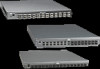
Replacing the cable guides (pillars) You can use cable guides (pillars) to organize the port cables into logical groups, such as port quads (sets of four neighboring ports). The cable pillars do not attach to the chassis. The cable pillars also serve to keep the cables evenly spaced and hold them away from the 16-port card to prevent them from bending to less than the minimum bend radius. CAUTION: Do not route the cables in front of the air exhaust vent, which is located at the top of the port side of the chassis. Arrange the cables so that the minimum bend radius is not exceeded; for a 50-micron cable, the minimum bend radius is 2 inches under full tensile load and 1.2 inches with no tensile load. Tie wraps are not recommended for optical cables because they are easily overtightened and can break the optical cables. To replace the cable pillars, orient them horizontally and insert the cables into the holes, using a separate hole for each cable (see "Manage cables" on page 47). Replacing a 16-port card and filler panel This section describes how to remove and replace 16-port cards (see Figure 22) and 16-port card filler panels (see Figure 23) from the switch. Preliminary steps Take the following steps before removing and replacing a 16-port card: 1. Check the LEDs. The LEDs are located on the front panel of each 16-port card (see Figure 15). Refer to "16-port cards" on page 64 for a description of the 16-port card LEDs. NOTE: The WWN bezel on the nonport side of the switch also displays a power and status LED for each 16-port card. 2. Establish a telnet or console session. Before replacing a 16-port card, establish a telnet or console connection to identify a failure and verify operation after replacement. For information about how to check the status of hardware components using the CLI, refer to the HP StorageWorks procedures user guide for the Fabric OS version running on your switch. 90 Installing FRUs
-
 1
1 -
2
-
3
-
4
-
5
-
6
-
7
-
8
-
9
-
10
-
11
-
12
-
13
-
14
-
15
-
16
-
17
-
18
-
19
-
20
-
21
-
22
-
23
-
24
-
25
-
26
-
27
-
28
-
29
-
30
-
31
-
32
-
33
-
34
-
35
-
36
-
37
-
38
-
39
-
40
-
41
-
42
-
43
-
44
-
45
-
46
-
47
-
48
-
49
-
50
-
51
-
52
-
53
-
54
-
55
-
56
-
57
-
58
-
59
-
60
-
61
-
62
-
63
-
64
-
65
-
66
-
67
-
68
-
69
-
70
-
71
-
72
-
73
-
74
-
75
-
76
-
77
-
78
-
79
-
80
-
81
-
82
-
83
-
84
-
 85
85 -
 86
86 -
 87
87 -
 88
88 -
 89
89 -
 90
90 -
 91
91 -
 92
92 -
 93
93 -
 94
94 -
 95
95 -
96
-
97
-
98
-
99
-
100
-
101
-
102
-
103
-
104
-
105
-
106
-
107
-
108
-
109
-
110
-
111
-
112
-
113
-
114
-
115
-
116
-
117
-
118
-
119
-
120
-
121
-
122
-
123
-
124
-
125
-
126
-
127
-
128
-
129
-
130
-
131
-
132
-
133
-
134
-
135
-
136
-
137
-
138
-
139
-
140
-
141
-
142
-
143
-
144
-
145
-
146
-
147
-
148
-
149
-
150
-
151
-
152
-
153
-
154
-
155
-
156
-
157
-
158
-
159
-
160
-
161
-
162
-
163
-
164
-
165
-
166
 |
 |
