HP dx2308 HP Compaq dx2300 and dx2308 Business PC Service Reference Guide, 1st - Page 58
\, Preparation for Disassembly, on Access Panel, Front Bezel
 |
View all HP dx2308 manuals
Add to My Manuals
Save this manual to your list of manuals |
Page 58 highlights
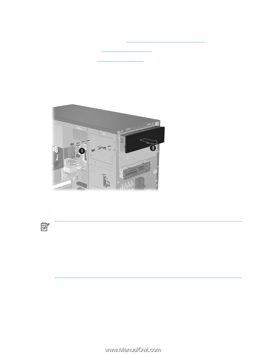
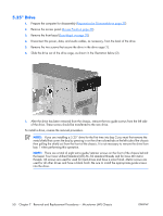
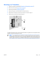
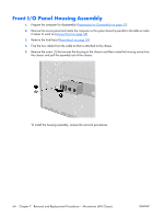
5.25" Drive 1. Prepare the computer for disassembly (Preparation for Disassembly on page 37) 2. Remove the access panel (Access Panel on page 38) 3. Remove the front bezel (Front Bezel on page 39) 4. Disconnect the power, data, and audio cables, as necessary, from the back of the drive. 5. Remove the two screws that secure the drive in the drive cage (1). 6. Slide the drive out of the drive cage, as shown in the illustration below (2). 7. After the drive has been removed from the chassis, remove the two guide screws from the left side of the drive. These screws should be transferred to the new drive. To install a drive, reverse the removal procedure. NOTE: If you are installing a 5.25" drive for the first time into bay 2 you must first remove the metal shield that covers the bay by pressing in on the silver-colored tab on the left side of the chassis then pulling the shield out from the front of the chassis. It is not necessary to remove the drive from bay 1 when performing this operation. NOTE: There are a total of eight extra guide/retainer screws on the front of the chassis behind the bezel. Four have Unified Standard (US) #6-32 standard threads and for have M3 metric threads. US screws are used for used for hard drives and have a silver finish. Metric screws are used for all other drives and have a black finish. Be sure to install the appropriate guide screws into the drive. 50 Chapter 7 Removal and Replacement Procedures- Microtower (MT) Chassis ENWW
-
 1
1 -
2
-
3
-
4
-
5
-
6
-
7
-
8
-
9
-
10
-
11
-
12
-
13
-
14
-
15
-
16
-
17
-
18
-
19
-
20
-
21
-
22
-
23
-
24
-
25
-
26
-
27
-
28
-
29
-
30
-
31
-
32
-
33
-
34
-
35
-
36
-
37
-
38
-
39
-
40
-
41
-
42
-
43
-
44
-
45
-
46
-
47
-
48
-
49
-
50
-
51
-
52
-
 53
53 -
 54
54 -
 55
55 -
 56
56 -
 57
57 -
 58
58 -
 59
59 -
 60
60 -
 61
61 -
 62
62 -
 63
63 -
64
-
65
-
66
-
67
-
68
-
69
-
70
-
71
-
72
-
73
-
74
-
75
-
76
-
77
-
78
-
79
-
80
-
81
-
82
-
83
-
84
-
85
-
86
-
87
-
88
-
89
-
90
-
91
-
92
-
93
-
94
-
95
-
96
-
97
-
98
-
99
-
100
-
101
-
102
 |
 |