Hitachi C8FSE Instruction Manual - Page 12
Before Using - accessories
 |
UPC - 717709012998
View all Hitachi C8FSE manuals
Add to My Manuals
Save this manual to your list of manuals |
Page 12 highlights
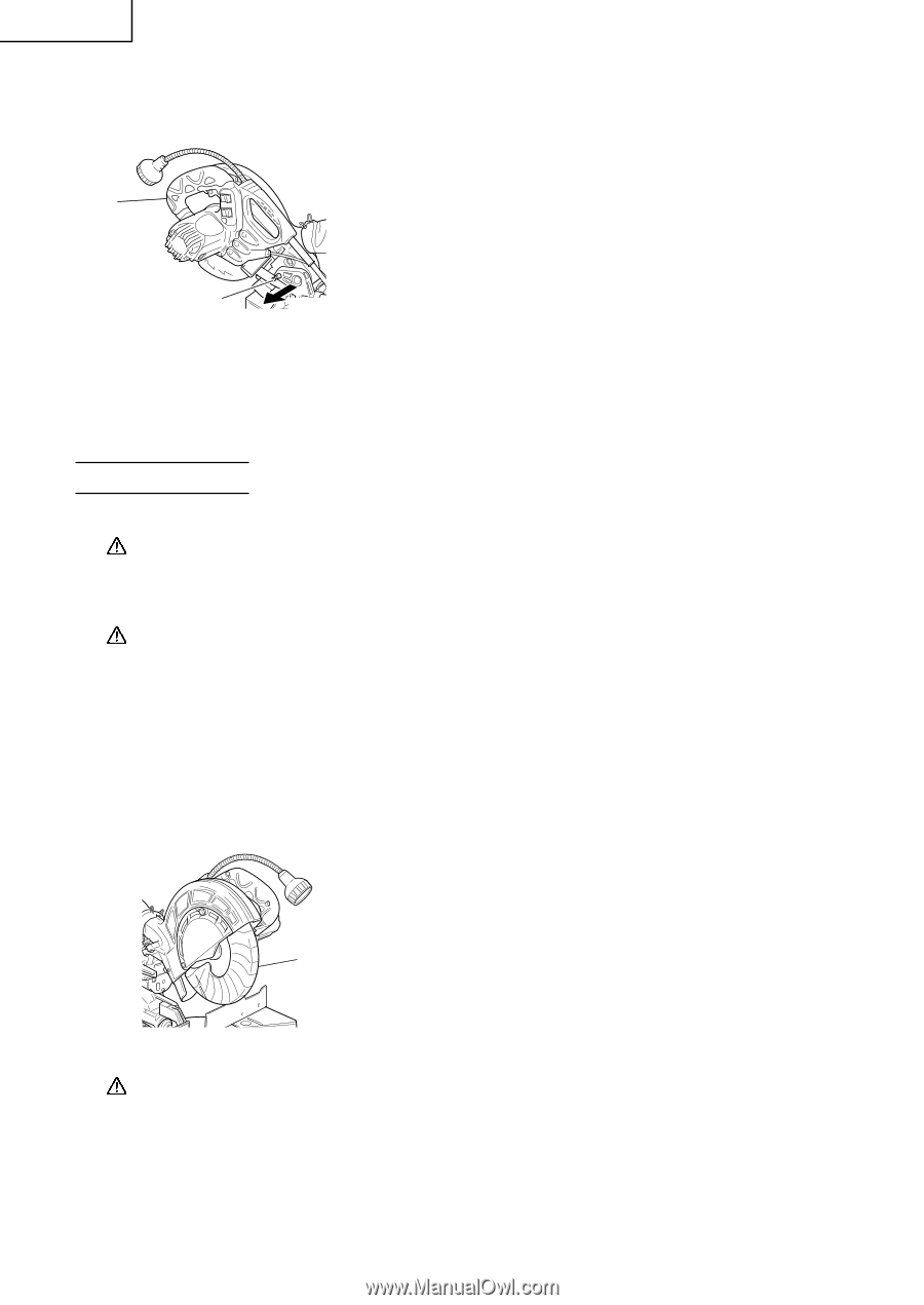
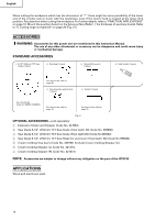
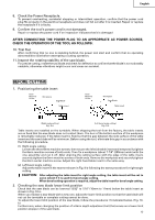
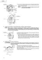
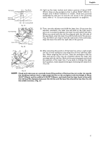
English 3. Releasing the locking pin Handle When the power tool is prepared for shipping, its main parts are secured by a locking pin. Move the handle slightly so that the locking pin can be disengaged. NOTE: Lowering the handle slightly will enable you to disengage the locking pin more easily and safely. The lock position of the locking pin is for carrying and storage only. Locking pin Pull Fig. 7 4. Installing the dust bag, holder, stopper and vises (The holder and stopper are optional accessories.) Attach the dust bag and vise assembly as indicated in Fig. 1 and Fig. 2. BEFORE USING 1. Make sure the power source is appropriate for the tool. WARNING: Never connect the power tool unless the available AC power source is of the same voltage as that specified on the nameplate of the tool. Never connect this power tool to a DC power source. 2. Make sure the trigger switch is turned OFF. WARNING: If the power cord is connected to the power source with the trigger switch turned ON the power tool will start suddenly and can cause a serious accident. 3. Check the saw blade for visible defects. Confirm that the saw blade is free of cracks or other visible damage. 4. Confirm that the saw blade is attached securely to the power tool. Using the supplied 10mm box wrench, tighten the bolt on the saw blade spindle to secure the saw blade. For details, see Fig. 47-a, Fig. 47-b, Fig. 47-c and Fig. 47-d in the section on "SAW BLADE MOUNTING AND DISMOUNTING". 5. Check the lower guard for proper operation. Lower guard is designed to protect the operator from coming into contact with the saw blade during operation of the tool. Always check that the lower guard moves smoothly and covers the saw blade properly. Lower guard Fig. 8 WARNING: NEVER OPERATE THE POWER TOOL if the safety cover does not function smoothly. 6. Confirm the position of the spindle lock before using the tool. After installing the saw blade, confirm that the spindle lock has been returned to the retract position before using the power tool (see Fig. 47-b). 7. Check the lower limit position of the Saw Blade. Although it was adjusted before shipment, carefully check the height of the saw blade. Confirm that the saw blade can be lowered 13/32" to 7/16" (10mm to 11mm) below the table insert. For details, see the section on "Checking the saw blade lower limit position". 12
-
 1
1 -
2
-
3
-
4
-
5
-
6
-
 7
7 -
 8
8 -
 9
9 -
 10
10 -
 11
11 -
 12
12 -
 13
13 -
 14
14 -
 15
15 -
 16
16 -
 17
17 -
18
-
19
-
20
-
21
-
22
-
23
-
24
-
25
-
26
-
27
-
28
-
29
-
30
-
31
-
32
-
33
-
34
-
35
-
36
-
37
-
38
-
39
-
40
-
41
-
42
-
43
-
44
-
45
-
46
-
47
-
48
-
49
-
50
-
51
-
52
-
53
-
54
-
55
-
56
-
57
-
58
-
59
-
60
-
61
-
62
-
63
-
64
-
65
-
66
-
67
-
68
-
69
-
70
-
71
-
72
-
73
-
74
-
75
-
76
-
77
-
78
-
79
-
80
-
81
-
82
-
83
-
84
-
85
-
86
-
87
-
88
-
89
-
90
-
91
-
92
-
93
-
94
-
95
-
96
 |
 |