Hitachi C8FSE Instruction Manual - Page 13
Before Cutting - factory
 |
UPC - 717709012998
View all Hitachi C8FSE manuals
Add to My Manuals
Save this manual to your list of manuals |
Page 13 highlights
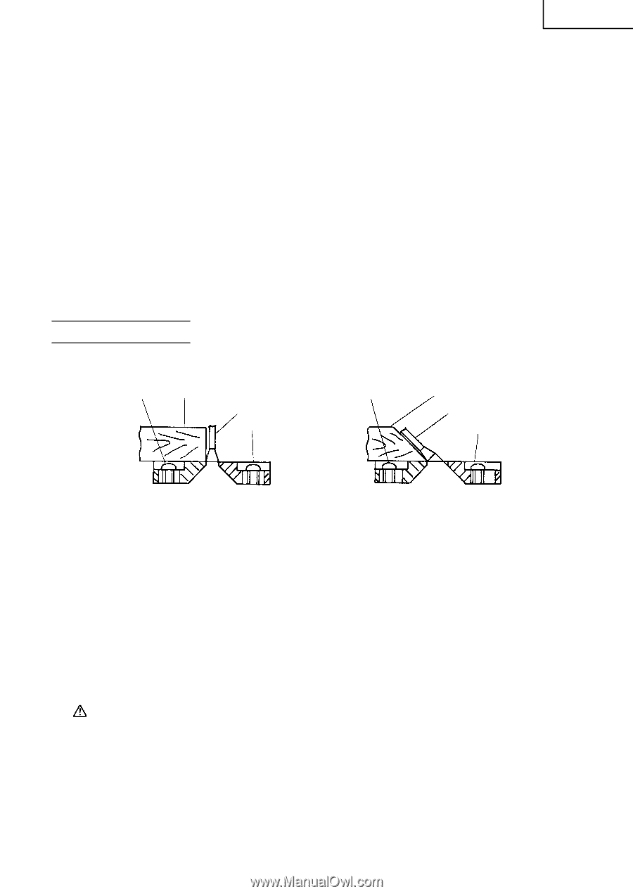
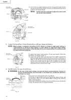
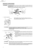
English 8. Check the Power Receptacle. To prevent overheating, accidental stopping or intermittent operation, confirm that the power cord plug fits properly in the electrical receptacle and does not fall out after it is inserted. Repair or replace the receptacle if it is faulty. 9. Confirm the tool's power cord is not damaged. Repair or replace the power cord if an inspection indicates that it is damaged AFTER CONNECTING THE POWER PLUG TO AN APPROPRIATE AC POWER SOURCE, CHECK THE OPERATION OF THE TOOL AS FOLLOWS: 10. Trial Run After confirming that no one is standing behind, the power tool start and confirm that no operating abnormalities exist before attempting a cutting operation. 11. Inspect the rotating stability of the saw blade. For precise cutting, rotate the saw blade and check for deflection to confirm that the blade is not noticeably unstable; otherwise vibrations might occur and cause an accident. BEFORE CUTTING 1. Positioning the table insert 6mm Machine Screw Workpiece Saw Blade Table insert 6mm Machine Screw Workpiece Saw Blade Table insert [Right angle cutting] Fig. 9-a [Left bevel angle cutting] Fig. 9-b Table inserts are installed on the turntable. When shipping the tool from the factory, the table inserts are so fixed that the saw blade does not contact them. The burr of the bottom surface of the workpiece is remarkably reduced, if the table insert is fixed so that the gap between the side surface of the table insert and the saw blade will be minimum. Before using the tool, eliminate this gap in accordance with the following procedure. (1) Right angle cutting Loosen the three 6mm machine screws, then secure the left side table insert and temporarily tighten the 6mm machine screws of both ends. Then fix a workpiece (about 7-7/8" (200mm) wide) with the vise assembly and cut it off. After aligning the cutting surface with the edge of the table insert, securely tighten the 6mm machine screws of both ends. Remove the workpiece and securely tighten the 6mm center machine screw. Adjust the right hand table insert in the same way. (2) Left bevel angle cutting Adjust the table insert in the manner shown in Fig. 9-b following the same procedure for right angle cutting. CAUTION: After adjusting the table insert for right angle cutting, the table insert will be cut to some extent if it is used for bevel angle cutting. When bevel cutting operation is required, adjust the table insert for bevel angle cutting. 2. Checking the saw blade lower limit position Check that the saw blade can be lowered 13/32" to 7/16" (10mm to 11mm) below the table insert as shown in Fig. 10-a. When you replace a saw blade with a new one, adjust the lower limit position so that the saw blade will not cut the turntable or complete cutting cannot be done. To adjust the lower limit position of the saw blade, follow the procedures (1) indicated below. (Fig. 10b) Furthermore, when changing the position of a 8mm depth adjustment bolt that serves as a lower limit position stopper of the saw blade. 13
-
 1
1 -
2
-
3
-
4
-
5
-
6
-
7
-
 8
8 -
 9
9 -
 10
10 -
 11
11 -
 12
12 -
 13
13 -
 14
14 -
 15
15 -
 16
16 -
 17
17 -
 18
18 -
19
-
20
-
21
-
22
-
23
-
24
-
25
-
26
-
27
-
28
-
29
-
30
-
31
-
32
-
33
-
34
-
35
-
36
-
37
-
38
-
39
-
40
-
41
-
42
-
43
-
44
-
45
-
46
-
47
-
48
-
49
-
50
-
51
-
52
-
53
-
54
-
55
-
56
-
57
-
58
-
59
-
60
-
61
-
62
-
63
-
64
-
65
-
66
-
67
-
68
-
69
-
70
-
71
-
72
-
73
-
74
-
75
-
76
-
77
-
78
-
79
-
80
-
81
-
82
-
83
-
84
-
85
-
86
-
87
-
88
-
89
-
90
-
91
-
92
-
93
-
94
-
95
-
96
 |
 |