Hitachi C8FSE Instruction Manual - Page 21
Miter cutting procedures, Compound cutting procedures - sliding compound miter saw
 |
UPC - 717709012998
View all Hitachi C8FSE manuals
Add to My Manuals
Save this manual to your list of manuals |
Page 21 highlights
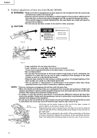
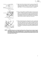
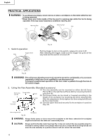
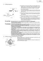
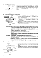
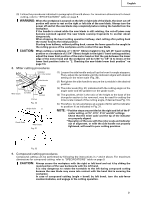
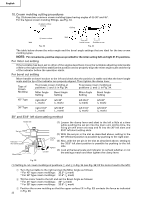
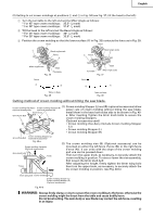
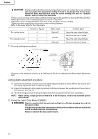
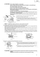
English (3) Follow the procedures indicated in paragraphs 4,5 and 6 above. For maximum dimensions for bevel cutting, refer to "SPECIFICATIONS" table on page 9. WARNING: When the workpiece is secured on the left or right side of the blade, the short cut-off portion will come to rest on the right or left side of the saw blade. Always turn the power off and let the saw blade stop completely before raising the handle from the workpiece. If the handle is raised while the saw blade is still rotating, the cut-off piece may become jammed against the saw blade causing fragments to scatter about dangerously. When stopping the bevel cutting operation halfway, start cutting after pulling back the motor head to the initial position. Starting from halfway, without pulling back, causes the lower guard to be caught in the cutting groove of the workpiece and to contact the saw blade. CAUTION: When cutting a workpiece of 1-15/16" (50mm) height in the left 45° bevel cutting position or a workpiece of 2-3/4" (70mm) height in the right 5° bevel cutting position, adjust the lower limit position of the motor head so that the gap between the lower edge of the motor head and the workpiece will be 5/64" to 1/8" (2 to 3mm) at the lower limit position (refer to "2. Checking the saw blade lower limit position" on page 13). 8. Miter cutting procedures Indicator (For miter scale) Side Handle Turntable Turn the Miter Scale turntable Tighten Lever Loosen Pull up Fig. 30 Angle Scale a Grade Scale Miter Scale Fig. 31 (1) Loosen the side handle and pull up the lever for angle stoppers. Then, adjust the turntable until the indicator aligns with desired setting on the miter scale (Fig. 30). (2) Re-tighten the side handle to secure the turntable in the desired position. (3) The miter scale (Fig. 31) indicates both the cutting angle on the angle scale and the gradient on the grade scale. (4) The gradient, which is the ratio of the height to the base of the triangular section to be removed, may be used for setting the miter scale instead of the cutting angle, if desired (see Fig. 31). (5) Therefore, to cut a workpiece at a grade of 2/10, set the indicator to position a as indicated in Fig. 31. NOTE: * Positive stops are provided at the right and left of the 0° center setting, at 15°, 22.5°, 31.6° and 45° settings. Check that the miter scale and the tip of the indicator are properly aligned. * Operation of the saw with the miter scale and indicator out of alignment, or with the side handle not properly tightened, will result in poor cutting precision. Fig. 32 9. Compound cutting procedures Compound cutting can be performed by following the instructions in 7 and 8 above. For maximum dimensions for compound cutting, refer to "SPECIFICATIONS" table on page 9. CAUTION: Always secure the workpiece with the right or left hand and cut it by sliding the round portion of the saw backwards with the left hand. It is very dangerous to rotate the turntable to the left during compound cutting because the saw blade may come into contact with the hand that is securing the workpiece. In case of compound cutting (angle + bevel) by left bevel, turn the sub-fence counterclockwise, and engage in the cutting operation. 21
-
 1
1 -
2
-
3
-
4
-
5
-
6
-
7
-
8
-
9
-
10
-
11
-
12
-
13
-
14
-
15
-
 16
16 -
 17
17 -
 18
18 -
 19
19 -
 20
20 -
 21
21 -
 22
22 -
 23
23 -
 24
24 -
 25
25 -
 26
26 -
27
-
28
-
29
-
30
-
31
-
32
-
33
-
34
-
35
-
36
-
37
-
38
-
39
-
40
-
41
-
42
-
43
-
44
-
45
-
46
-
47
-
48
-
49
-
50
-
51
-
52
-
53
-
54
-
55
-
56
-
57
-
58
-
59
-
60
-
61
-
62
-
63
-
64
-
65
-
66
-
67
-
68
-
69
-
70
-
71
-
72
-
73
-
74
-
75
-
76
-
77
-
78
-
79
-
80
-
81
-
82
-
83
-
84
-
85
-
86
-
87
-
88
-
89
-
90
-
91
-
92
-
93
-
94
-
95
-
96
 |
 |
