Hitachi C8FSE Instruction Manual - Page 24
Groove cutting procedures, Cutting depth adjustment procedure, Using the Light Only Model C8FSHE - blade size
 |
UPC - 717709012998
View all Hitachi C8FSE manuals
Add to My Manuals
Save this manual to your list of manuals |
Page 24 highlights
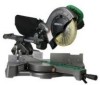
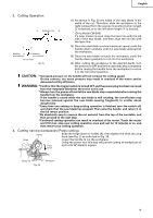
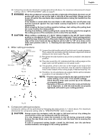
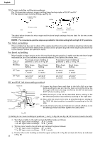
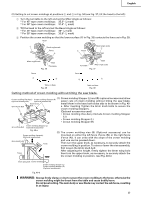
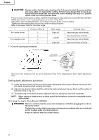
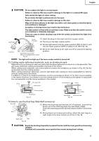
English CAUTION: Always confirm that the motor head (see Fig. 1) does not contact the crown molding vise ass'y when it is lowered for cutting. If there is any danger that it may do so, loosen the 6mm knob bolt and move the crown molding vise ass'y to a position where it will not contact the saw blade. Position crown molding with its WALL CONTACT EDGE against the guide fence and its CEILING CONTACT EDGE against the crown molding Stoppers as shown in Fig. 40-b. Adjust the crown molding Stoppers according to the size of the crown molding. Tighten the 6mm wing bolt to secure the crown molding Stoppers. Refer to the lower table for the miter angle. For inside corner For outside corner Position in Fig. 34 1 2 3 4 Miter angle Right 45° Left 45° Right 45° Finished piece Save the right side of blade Save the left side of blade Save the right side of blade Save the left side of blade 11. Groove cutting procedures Cut grooves with saw blade 6mm Depth adjustment bolt Turn a Hinge b Fig. 41 Fig. 42 Grooves in the workpiece can be cut as indicated in Fig. 41 by adjusting the 6mm depth adjustment bolt. Cutting depth adjustment procedure: (1) Lower the motor head, and turn the 6 mm depth adjustment bolt by hand. (Where the head of the 6 mm depth adjustment bolt contacts the hinge.) (2) Adjust to the desired cutting depth by setting the distance between the saw blade and the surface of the base (see b in Fig. 41). (3) The 8mm wing nut must be properly tightened after the adjustment has been completed. NOTE: When cutting a single groove at either end of the workpiece, remove the unneeded portion with a chisel. 12. Using the Light (Only Model C8FSHE) WARNING: Check to ascertain that the main unit and light are off before plugging the cord into the power socket. The light lens reaches high temperatures during and immediately after use and should not be touched under any circumstances. Failure to observe this may result in burns. 24
-
 1
1 -
2
-
3
-
4
-
5
-
6
-
7
-
8
-
9
-
10
-
11
-
12
-
13
-
14
-
15
-
16
-
17
-
18
-
 19
19 -
 20
20 -
 21
21 -
 22
22 -
 23
23 -
 24
24 -
 25
25 -
 26
26 -
 27
27 -
 28
28 -
 29
29 -
30
-
31
-
32
-
33
-
34
-
35
-
36
-
37
-
38
-
39
-
40
-
41
-
42
-
43
-
44
-
45
-
46
-
47
-
48
-
49
-
50
-
51
-
52
-
53
-
54
-
55
-
56
-
57
-
58
-
59
-
60
-
61
-
62
-
63
-
64
-
65
-
66
-
67
-
68
-
69
-
70
-
71
-
72
-
73
-
74
-
75
-
76
-
77
-
78
-
79
-
80
-
81
-
82
-
83
-
84
-
85
-
86
-
87
-
88
-
89
-
90
-
91
-
92
-
93
-
94
-
95
-
96
 |
 |