Hitachi C8FSE Instruction Manual - Page 26
Saw Blade Mounting And Dismounting - lower guard installation
 |
UPC - 717709012998
View all Hitachi C8FSE manuals
Add to My Manuals
Save this manual to your list of manuals |
Page 26 highlights
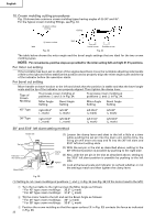
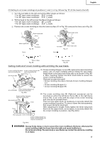
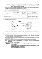
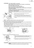
English SAW BLADE MOUNTING AND DISMOUNTING WARNING: * To prevent an accident or personal injury, always turn off the trigger switch and disconnect the power plug from the receptacle before removing or installing a saw blade. If cutting work is done in a state where the bolt is not sufficiently tightened, the bolt can get loose, the blade can come off, and the lower guard can get damaged, resulting in injuries. Also, check that the bolts are properly tightened before plugging the power plug into the receptacle. * If the bolts are attached or detached using tools other than the 10mm box wrench (standard accessory), excessive or improperly tightening occurs, resulting in injury. 1. Mounting the saw blade (Fig. 47-a, Fig. 47-b, Fig. 47-c and Fig. 47-d) (1) Use the accessory 10mm box wrench to loosen the 6mm bolt fastening the spindle cover and then remove the spindle cover. (2) Press in spindle lock and loosen bolt with 10mm box wrench (standard accessory). Since the bolt is left-hand threaded, loosen by turning it to the right as shown in Fig. 47-c. NOTE: If the spindle lock cannot be easily pressed in to lock the spindle, turn the bolt with 10mm box wrench (standard accessory) while applying pressure on the spindle lock. The saw blade spindle is locked when the spindle lock is pressed inward. (3) Remove the bolt and washer (D) 6mm Bolt Spindle Cover Spindle Lock 5/8" (15.9mm) Fig. 47-a Spindle Lock 10 mm Box Wrench Tighten Fig. 47-b Saw blade Bolt Loosen Washer (D) Lower Guard Bolt Fig. 47-c Washer (D) Fig. 47-d Washer (D) (4) Lift the lower guard and mount the saw blade. WARNING: When mounting the saw blade, confirm that the rotation indicator mark on the saw blade and the rotation direction of the gear case(see Fig. 1) are properly matched. (5) Thoroughly clean washer (D) and the bolt, and install them onto the saw blade spindle. (6) Press in the spindle lock and tighten the bolt by turning it to the left by standard accessorie's wrench (10mm box wrench) as indicated in Fig. 47-c. CAUTION: * A dust guide is installed inside behind the gear case. When removing or installing the saw blade, do not make contact with the dust guide. Contact may break or chip saw blade tips. * Confirm that the spindle lock has returned to the retract position after installing or removing the saw blade. * Tighten the bolt so it does not come loose during operation. Confirm the bolt has been properly tightened before the power tool is started. 26
-
 1
1 -
2
-
3
-
4
-
5
-
6
-
7
-
8
-
9
-
10
-
11
-
12
-
13
-
14
-
15
-
16
-
17
-
18
-
19
-
20
-
 21
21 -
 22
22 -
 23
23 -
 24
24 -
 25
25 -
 26
26 -
 27
27 -
 28
28 -
 29
29 -
 30
30 -
 31
31 -
32
-
33
-
34
-
35
-
36
-
37
-
38
-
39
-
40
-
41
-
42
-
43
-
44
-
45
-
46
-
47
-
48
-
49
-
50
-
51
-
52
-
53
-
54
-
55
-
56
-
57
-
58
-
59
-
60
-
61
-
62
-
63
-
64
-
65
-
66
-
67
-
68
-
69
-
70
-
71
-
72
-
73
-
74
-
75
-
76
-
77
-
78
-
79
-
80
-
81
-
82
-
83
-
84
-
85
-
86
-
87
-
88
-
89
-
90
-
91
-
92
-
93
-
94
-
95
-
96
 |
 |
