Hitachi C8FSE Instruction Manual - Page 18
Practical Applications
 |
UPC - 717709012998
View all Hitachi C8FSE manuals
Add to My Manuals
Save this manual to your list of manuals |
Page 18 highlights
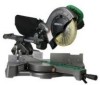
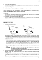
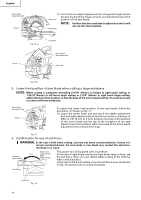
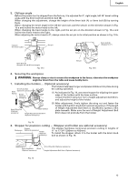
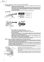
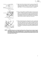
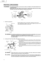
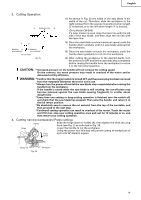
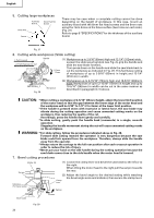
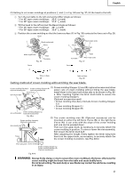
English PRACTICAL APPLICATIONS WARNING: * To avoid personal injury, never remove or place a workpiece on the table while the tool is being operated. * Never place your limbs inside of the line next to warning sign while the tool is being operated. This may cause hazardous conditions (see Fig. 22). Line Warning Sign Warning Sign Line 1. Switch operation Hole Trigger switch Fig. 22 Pull the trigger to turn on the switch, release it to shut it off. After releasing the trigger, make sure the trigger has gone all the way back and the switch is turned off. Fig. 23 WARNING: This will ensure that the power tool cannot be turned on accidentally or by someone (especially a child) who is not qualified to use the power tool. To prevent unauthorized operation of this tool, insert a padlock through the hole in the switch trigger. 2. Using the Vise Assembly (Standard accessory) (1) The vise assembly can be mounted on either the left fence 6mm wing bolt (B) Screw holder {Fence (B)} or the right fence {Fence (A)} by loosening the 6mm Knob wing bolt (A). (2) The screw holder can be raised or lowered according to the Vise plate height of the workpiece by loosening the 6mm wing bolt (B). After the adjustment, firmly tighten the 6mm wing bolt (B) and Fence Vise shaft fix the screw holder. (3) Turn the upper knob and securely fix the workpiece in position (Fig. 24). 6mm wing bolt (A) Fig. 24 Workpiece WARNING: Always firmly clamp or vise to secure the workpiece to the fence; otherwise the workpiece might be thrust from the table and cause bodily harm. CAUTION: Always confirm that the motor head (see Fig. 1) does not contact the vise assembly when it is lowered for cutting. If there is any danger that it may do so, loosen the 6 mm wing bolt (B) and move the vise assembly to a position where it will not contact the saw blade. 18
-
 1
1 -
2
-
3
-
4
-
5
-
6
-
7
-
8
-
9
-
10
-
11
-
12
-
 13
13 -
 14
14 -
 15
15 -
 16
16 -
 17
17 -
 18
18 -
 19
19 -
 20
20 -
 21
21 -
 22
22 -
 23
23 -
24
-
25
-
26
-
27
-
28
-
29
-
30
-
31
-
32
-
33
-
34
-
35
-
36
-
37
-
38
-
39
-
40
-
41
-
42
-
43
-
44
-
45
-
46
-
47
-
48
-
49
-
50
-
51
-
52
-
53
-
54
-
55
-
56
-
57
-
58
-
59
-
60
-
61
-
62
-
63
-
64
-
65
-
66
-
67
-
68
-
69
-
70
-
71
-
72
-
73
-
74
-
75
-
76
-
77
-
78
-
79
-
80
-
81
-
82
-
83
-
84
-
85
-
86
-
87
-
88
-
89
-
90
-
91
-
92
-
93
-
94
-
95
-
96
 |
 |