Hitachi C8FSE Instruction Manual - Page 17
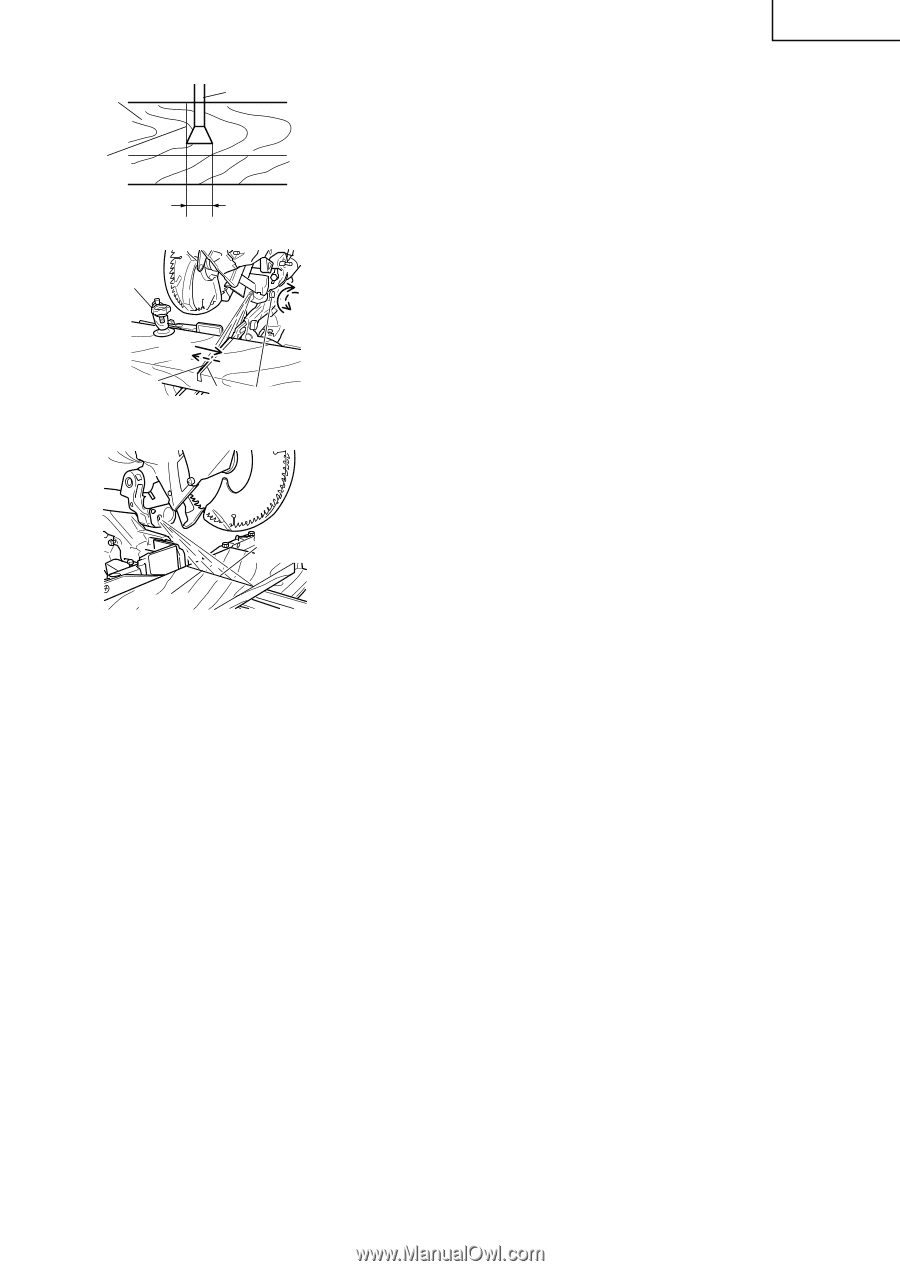
line width 0.5mm]. Fig. 21
 |
UPC - 717709012998
View all Hitachi C8FSE manuals
Add to My Manuals
Save this manual to your list of manuals |
Page 17 highlights
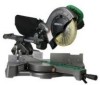
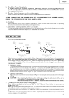
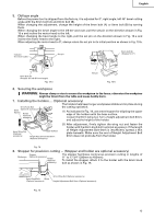
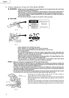
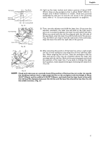
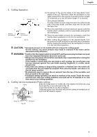
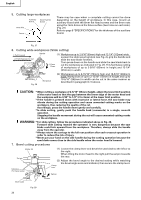
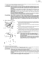
English Workpiece Saw Blade Marking (pre-marked) Cutting Width Fig. 19 Vise Assembly Move Turn Laser Line Groove Adjuster Fig. 20 (1) Light up the laser marker and make a groove of about 3/16" (5mm) deep on the workpiece that is about 25/32" (20mm) in height and 5-29/32"(150mm) in width. Hold the grooved workpiece by vise as it is and do not move it. For grooving work, refer to "11. Groove cutting procedures" on page 24. (2) Then, turn the adjuster and shift the laser line. (If you turn the adjuster clockwise, the laser line will shift to the right and if you turn it counterclockwise, the laser line will shift to the left.) When you work with the ink line aligned with the left side of the saw blade, align the laser line with the left end of the groove. (Fig. 20) When you align it with the right side of the saw blade, align the laser line with the right side of the groove. Laser Line (3) After adjusting the position of the laser line, draw a right-angle ink line on the workpiece and align the ink line with the laser line. When aligning the ink line, slide the workpiece little by little and secure it by vise at a position where the laser line overlaps with the ink line. Work on the grooving again and check the position of the laser line. If you wish to change the laser line's position, make adjustments again following the steps from (1) to (3). Marking (pre-marked) Fig. 21 NOTE: Check and make sure on a periodic basis if the position of the laser line is in order. As regards the checking method, draw a right-angle ink line on the workpiece with the height of about 25/32" (20mm) and the width of 5-29/32"(150mm), and check that the laser line is in line with the ink line [The deviation between the ink line and the laser line should be less than the ink line width (0.5mm)]. (Fig. 21) 17
-
 1
1 -
2
-
3
-
4
-
5
-
6
-
7
-
8
-
9
-
10
-
11
-
 12
12 -
 13
13 -
 14
14 -
 15
15 -
 16
16 -
 17
17 -
 18
18 -
 19
19 -
 20
20 -
 21
21 -
 22
22 -
23
-
24
-
25
-
26
-
27
-
28
-
29
-
30
-
31
-
32
-
33
-
34
-
35
-
36
-
37
-
38
-
39
-
40
-
41
-
42
-
43
-
44
-
45
-
46
-
47
-
48
-
49
-
50
-
51
-
52
-
53
-
54
-
55
-
56
-
57
-
58
-
59
-
60
-
61
-
62
-
63
-
64
-
65
-
66
-
67
-
68
-
69
-
70
-
71
-
72
-
73
-
74
-
75
-
76
-
77
-
78
-
79
-
80
-
81
-
82
-
83
-
84
-
85
-
86
-
87
-
88
-
89
-
90
-
91
-
92
-
93
-
94
-
95
-
96
 |
 |