Husqvarna AUTOMOWER 435X AWD Owner Manual - Page 25
To examine where to put the guide wire, Work area examples, Installation of the product
 |
View all Husqvarna AUTOMOWER 435X AWD manuals
Add to My Manuals
Save this manual to your list of manuals |
Page 25 highlights
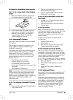
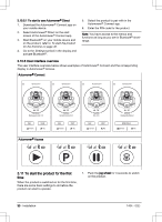
3.4.4 To examine where to put the guide wire Put the guide wire from the charging station through the work area and connect it to the boundary wire. This product has 2 guide wires. Use the same approach for all guide wires. • Put the guide wire in a line at a minimum of 2 m / 7 ft. in front of the charging station. • Make sure that the guide wire has as much free area as possible to the left of the guide wire when facing the charging station. • Put the guide wire minimum 30 cm / 12 in. from the boundary wire. • Do not make sharp bends when you install the guide wire. • If the work area has a slope, put the guide wire in a straight line from the bottom of the slope to the top of the slope. If it is not possible to make a straight line, put the guide wire diagonally across the slope. 3.4.5 Work area examples • If the charging station is put in a small area (A), make sure that the distance to the boundary wire is at a minimum 3 m / 10 ft. in front of the charging station. • If the work area has a passage (B), make sure that the distance to the boundary wire is at a minimum 2 m / 6.5 ft. If the passage is smaller than 2 m / 6.5 ft., install a guide wire through the passage. Minimum passage between the boundary wire is 60 cm / 24 in. • If the work area has areas which are connected by a narrow passage (B), you can set the product to first follow and then leave the guide wire after a certain distance (C). The settings can be changed in Lawn coverage on page 33. • If the work area includes a secondary area (D), refer to To make a secondary area on page 24. Put the product in the secondary area and select Secondary area mode. D A B C CAUTION: Do not put the guide wire in parallel with the slope, as the illustration shows. This can increase the wear on the grass. 3.5 Installation of the product 3.5.1 Installation tools • Hammer/plastic mallet: To simplify putting the stakes into the ground. 1404 - 002 - Installation - 25
-
 1
1 -
2
-
3
-
4
-
5
-
6
-
7
-
8
-
9
-
10
-
11
-
12
-
13
-
14
-
15
-
16
-
17
-
18
-
19
-
 20
20 -
 21
21 -
 22
22 -
 23
23 -
 24
24 -
 25
25 -
 26
26 -
 27
27 -
 28
28 -
 29
29 -
 30
30 -
31
-
32
-
33
-
34
-
35
-
36
-
37
-
38
-
39
-
40
-
41
-
42
-
43
-
44
-
45
-
46
-
47
-
48
-
49
-
50
-
51
-
52
-
53
-
54
-
55
-
56
-
57
-
58
-
59
-
60
-
61
-
62
-
63
-
64
-
65
-
66
-
67
-
68
 |
 |
