Husqvarna AUTOMOWER 435X AWD Owner Manual - Page 27
To install the boundary wire, To install, the boundary wire
 |
View all Husqvarna AUTOMOWER 435X AWD manuals
Add to My Manuals
Save this manual to your list of manuals |
Page 27 highlights
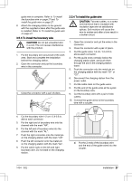
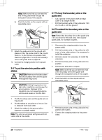
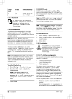
guide wire is complete. Refer to To install the boundary wire on page 27 and To install the guide wire on page 27. 8. Attach the charging station to the ground with the supplied screws after the guide wire is installed. Refer to To install the guide wire on page 27. 3.5.3 To install the boundary wire CAUTION: Do not put unwanted wire in a coil. The coil causes interference with the product. 1. Put the boundary wire around all of the work area. Start and complete the installation behind the charging station. 2. Open the connector and put the boundary wire in the connector. 3. Close the connector with a pair of pliers. 3.5.4 To install the guide wire CAUTION: Twinned cables, or a screw terminal block that is insulated with insulation tape are not satisfactory splices. Soil moisture will cause the wire to oxidize and after a time result in a broken circuit. 1. Open the connector and put the wires in the connector. 2. Close the connector with a pair of pliers. 3. Cut the guide wires 1-2 cm / 0.4-0.8 in. above each connector. 4. Put the guide wires centrally below the charging station plate, and push them through the slot in the charging station tower. 5. Push the connector onto the metal pin on the charging station with the mark "G1" or "G2". 6. Disconnect the charging station from the power outlet. 7. Put the cable mark on the guide wires. 8. Put the end of the guide wires at the eyelet on the boundary wire. 9. Cut the boundary wire with a pair of wire cutters. 10. Connect the guide wires to the boundary wire with a coupler. 4. Cut the boundary wire 1-2 cm / 0.4-0.8 in. above each connector. 5. Put the right end of boundary wire into the channel with the mark "AR". 6. Put the left end of boundary wire into the channel with the mark "AL". 7. Push the right connector onto the metal pin on the charging station with the mark "AR". 8. Push the left connector onto the metal pin on the charging station with the mark "AL". 9. Put the cable mark on the left and right boundary wire. Do not walk on the charging station. a) Put the 2 ends of the boundary wire and the end of the guide wires into the coupler. 1404 - 002 - Installation - 27
-
 1
1 -
2
-
3
-
4
-
5
-
6
-
7
-
8
-
9
-
10
-
11
-
12
-
13
-
14
-
15
-
16
-
17
-
18
-
19
-
20
-
21
-
 22
22 -
 23
23 -
 24
24 -
 25
25 -
 26
26 -
 27
27 -
 28
28 -
 29
29 -
 30
30 -
 31
31 -
 32
32 -
33
-
34
-
35
-
36
-
37
-
38
-
39
-
40
-
41
-
42
-
43
-
44
-
45
-
46
-
47
-
48
-
49
-
50
-
51
-
52
-
53
-
54
-
55
-
56
-
57
-
58
-
59
-
60
-
61
-
62
-
63
-
64
-
65
-
66
-
67
-
68
 |
 |
