IBM 621858U Installation Guide - Page 21
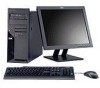
FireWire, connectors, Microphone, connector, green, System-error, drive, activity, Ethernet, Power-
 |
UPC - 000435883148
View all IBM 621858U manuals
Add to My Manuals
Save this manual to your list of manuals |
Page 21 highlights
IEEE 1394 (FireWire) connectors Use these connectors (four-pin on the front and six-pin on the rear) to connect FireWire devices, such as digital video cameras and external hard disk drives. USB connectors Use these connectors to connect USB devices to the computer, using redundant Plug and Play technology. Microphone connector (pink) Use this connector to connect a microphone to the computer when you want to record voices or other sounds on the hard disk. You can also use this connector (and a microphone) with speech-recognition software. Line out connector (green) Use this connector to send audio signals from the computer to external devices, such as speakers with built-in amplifiers, headphones, multimedia keyboards, or the audio line-in jack on a stereo system. System-error LED When this LED is lit, it indicates that a system error has occurred. An LED on the system board might also be lit to help isolate the error. If the system board LED is not lit, check the error log. Hard disk drive activity LED When this LED is lit, it indicates that the hard disk drive is in use. Ethernet activity LED When this LED is lit, it indicates that there is activity between the computer and the network. There are two of these LEDs, one on the front and one on the rear of the computer. Power-on LED When this LED is lit, it indicates that the computer is turned on. Power-control button Press this button to turn the computer on or off. Ethernet link status LED When this LED is flickering, it indicates that there is an active connection on the Ethernet connector. This LED is on the rear of the computer. Chapter 1. Introduction 9
-
 1
1 -
2
-
3
-
4
-
5
-
6
-
7
-
8
-
9
-
10
-
11
-
12
-
13
-
14
-
15
-
 16
16 -
 17
17 -
 18
18 -
 19
19 -
 20
20 -
 21
21 -
 22
22 -
 23
23 -
 24
24 -
 25
25 -
 26
26 -
27
-
28
-
29
-
30
-
31
-
32
-
33
-
34
-
35
-
36
-
37
-
38
-
39
-
40
-
41
-
42
-
43
-
44
-
45
-
46
-
47
-
48
-
49
-
50
-
51
-
52
-
53
-
54
-
55
-
56
-
57
-
58
-
59
-
60
-
61
-
62
-
63
-
64
-
65
-
66
-
67
-
68
-
69
-
70
-
71
-
72
-
73
-
74
-
75
-
76
-
77
-
78
 |
 |
