IBM 847691U Hardware Maintenance Manual
IBM 847691U - Netfinity 3000 - 91U Manual
 |
View all IBM 847691U manuals
Add to My Manuals
Save this manual to your list of manuals |
IBM 847691U manual content summary:
- IBM 847691U | Hardware Maintenance Manual - Page 1
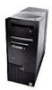
Netfinity Servers IBM Netfinity 3000 - Type 8476 Hardware Maintenance Manual March 2000 We Want Your Comments! (Please see page 256) S10L-9798-05 This Manual Supports The Following Models: 10U, 10X, 11U, 11X, 15U, 15X, 16U, 16X, 20U, 20X, 21U, 21X, 30U, 30X, 31U, 31X, 40U, 40X, 41U, 41X, 50U, 50X - IBM 847691U | Hardware Maintenance Manual - Page 2
- IBM 847691U | Hardware Maintenance Manual - Page 3
IBM Netfinity Servers IBM Netfinity 3000 - Type 8476 Hardware Maintenance Manual March 2000 We Want Your Comments! (Please see page 256) S10L-9798-05 IBM - IBM 847691U | Hardware Maintenance Manual - Page 4
this information and the product it supports, be sure to read the general information under "Notices" in the manual. Sixth Edition (March 2000) The was developed for products and services offered in the United States of America. IBM may not offer the products, services, or features discussed in this - IBM 847691U | Hardware Maintenance Manual - Page 5
, error messages, and configuration information for the Netfinity 3000 - Type 8476. Important This manual is intended for trained servicers who are familiar with IBM PC Server products. Before servicing an IBM product, be sure to review "Safety information" on page 212. Important Safety Information - IBM 847691U | Hardware Maintenance Manual - Page 6
is: http://www.ibm.com/pc/files.html The IBM BBS can be reached at (919) 517-0001. IBM online addresses: The HMM manuals online address is: http://www.ibm.com/pc/us/cdt/hmm.html The IBM Support Page is: http://www.ibm.com/support/ The IBM Personal computing solutions page. http://www.ibm.com/pc/ iv - IBM 847691U | Hardware Maintenance Manual - Page 7
this supplement iii Important Safety Information iii Online support iv IBM Netfinity 3000 - Type 8476 1 General Checkout 4 Diagnostics 6 Features 15 Additional service information 17 Locations 58 Symptom-to-FRU index 160 Undetermined problems 198 Parts listing (Netfinity 3000 - Type 8476 - IBM 847691U | Hardware Maintenance Manual - Page 8
vi Netfinity Server HMM - IBM 847691U | Hardware Maintenance Manual - Page 9
log 14 SIMM/DIMM errors 14 Features 15 Additional service information 17 Configuration overview 18 Configuration conflicts 20 Hardware the Ethernet controller 38 Troubleshooting the 10/100 Mbps Ethernet Controller 40 Network connection problems 40 © Copyright IBM Corp. 2000 1 - IBM 847691U | Hardware Maintenance Manual - Page 10
Diagnostic LEDs 41 Erasing lost or forgotten passwords 42 Power supply 45 ROM operation mode switch setting 47 SCSISelect utility program 49 Starting the SCSISelect utility program . . . . 49 SCSISelect utility program choices 49 Configure/View host adapter settings . . . . 49 SCSI disk - IBM 847691U | Hardware Maintenance Manual - Page 11
beep symptoms 160 Beep symptoms 160 POST error codes 163 Diagnostic error codes 167 Ethernet controller messages 189 Miscellaneous symptoms 191 SCSI messages 197 Undetermined problems 198 Parts listing (Netfinity 3000 - Type 8476) . . . . . 199 System 200 Keyboards 207 Power cords 209 - IBM 847691U | Hardware Maintenance Manual - Page 12
8476 servers. Attention The drives in the system you are servicing might have been rearranged or the drive startup sequence changed. Be the error-return code at test completion. General error messages appear if a problem or conflict is found by an application program, the operating system, or both - IBM 847691U | Hardware Maintenance Manual - Page 13
unusual response occurs, go to "Symptom-to-FRU index" on page 160. 8. For power supply problems, see "Power supply" on page 45. 001 IS THE SYSTEM PART OF A CLUSTER? Yes No the diagnostics version level). 2. Readable instructions or the Main Menu. (Step 004 continues) IBM Netfinity 3000 - Type 8476 5 - IBM 847691U | Hardware Maintenance Manual - Page 14
you cannot continue, replace the last device tested. Diagnostics The following tools are available to help identify and resolve hardware-related problems: Diagnostic test programs Power-on self-test (POST) POST beep codes Error messages Troubleshooting charts Option diskettes 6 Netfinity Server HMM - IBM 847691U | Hardware Maintenance Manual - Page 15
hardware configuration. This information might be useful in helping to isolate problems related to the operating system and device drivers. The IBM Enhanced Diagnostics Diskette also contains additional diagnostic programs for non-IBM devices. See "Running the diagnostic test programs" on page 11 - IBM 847691U | Hardware Maintenance Manual - Page 16
because of BIOS shadowing in RAM. If POST finishes without detecting any problems, the first screen of the operating system or application program appears (if page 27.) If Power-On Status is set to [Enabled] and POST detects a problem, you will hear multiple beeps or no beep. In most cases, an error - IBM 847691U | Hardware Maintenance Manual - Page 17
Troubleshooting and servicing of complex problems indicated by error messages should be performed by a trained service problem with the server hardware. The messages present text information that can be used to identify a failing part. These error messages are alphanumeric. Follow the instructions - IBM 847691U | Hardware Maintenance Manual - Page 18
or conflict is found by an application program, the operating system, or both. Error messages for operating-system and other software problems are generally text messages, but they also can be numeric messages. For information about these software error messages, refer to the information that - IBM 847691U | Hardware Maintenance Manual - Page 19
it in a safe place for later use. Make a backup copy of the IBM Enhanced Diagnostics information on a diskette. To do this: 1. Insert a blank, following instructions. 1. Write down all error code numbers and descriptions that appear on the screen as you start the server. (Note that a single problem - IBM 847691U | Hardware Maintenance Manual - Page 20
In the case of most errors, the Configuration/Setup Utility program starts automatically so that you can attempt to identify and correct the problem. When the Configuration/Setup Utility program starts, a screen titled POST Startup Errors appears. (Note that the POST Startup Errors screen does not - IBM 847691U | Hardware Maintenance Manual - Page 21
the operating system will start automatically (unless there is an unresolved problem with the startup device). Attention If you did not change any is an unresolved problem with the startup device). e. To exit from the Configuration/Setup Utility program, press Esc and follow the instructions on the - IBM 847691U | Hardware Maintenance Manual - Page 22
Press F3 again to save the file to diskette or F2 to print the file. SIMM/DIMM errors : SIMM/DIMM error messages issued by the IBM PC Enhanced Diagnostics: Message 2xx-1y 2xx-2y Corrupt BIOS Test aborted by user Failure Found A memory error was detected in SIMM socket Y A memory error - IBM 847691U | Hardware Maintenance Manual - Page 23
CD-ROM Drive Standard: IDE Keyboard and Auxiliary Device Keyboard Mouse Expansion Slot Connectors Supports up to seven adapters: Three dedicated ISA slot connectors Three dedicated PCI slot passwords Security-error indicator Selectable drive-startup sequence IBM Netfinity 3000 - Type 8476 15 - IBM 847691U | Hardware Maintenance Manual - Page 24
Side cover lock Unattended start mode SCSI Features 16-bit UltraSCSI adapter - One external connector - One internal connector Four bays available for internal SCSI hard disk drives Power Supply 330 Watts Auto-sensing function Built-in overload and surge protection Integrated Functions Voltage - IBM 847691U | Hardware Maintenance Manual - Page 25
information The following additional service information supports Netfinity 3000 - Type 8476 server. "Configuration overview" on page 18. "Configuration conflicts" on on page 49. "Specifications (Ethernet cable)" on page 53. "Specifications (system)" on page 56. IBM Netfinity 3000 - Type 8476 17 - IBM 847691U | Hardware Maintenance Manual - Page 26
Component Interconnect (PCI) Industry Standard Architecture (ISA) Small Computer System Interface (SCSI) Accelerated Graphics Port (AGP) accessing the following World Wide Web address: http://www.ibm.com/pc/us/compat/ Jumpers and switches are used to Reading the instructions 18 Netfinity Server HMM - IBM 847691U | Hardware Maintenance Manual - Page 27
system board. 3. Set jumpers or switches on the device. See the device installation instructions. 4. Install the device in the server. Reserve ISA legacy resources for ISA adapters. to the information that comes with the IBM ServerGuide package for more information. IBM Netfinity 3000 - Type 8476 19 - IBM 847691U | Hardware Maintenance Manual - Page 28
system board functions use. Record the current settings before making any changes. (See "Configuration/Setup utility program" on page 21 for instructions.) 2. Determine which adapter or device is causing the conflict. 3. Change adapter jumpers or switches. Some devices use jumpers and switches to - IBM 847691U | Hardware Maintenance Manual - Page 29
diagram inside the server. 5. Remove the device or adapter. Some configurations are not supported. If you must remove an adapter, see "Installing or removing ISA and PCI adapters program if you receive an error message instructing you to do so. If you installed or removed SCSI devices, run the - IBM 847691U | Hardware Maintenance Manual - Page 30
options, a message appears, indicating that a configuration change has occurred. You are then prompted to enter the Configuration/Setup Utility program to manually update the configuration settings or to confirm and save the settings that were automatically updated by the system programs. After you - IBM 847691U | Hardware Maintenance Manual - Page 31
Utility program, but you cannot change any settings. 4. If a configuration error occurs, a prompt appears before the operating system starts ( see "Configuration conflicts" on page 20). IBM Netfinity 3000 - Type 8476 23 - IBM 847691U | Hardware Maintenance Manual - Page 32
. In the Configuration/Setup Utility program menus, you can accept the configuration changes by viewing and saving the changes, or you can make manual changes and then save the settings. The following is a quick reference for identifying symbols in the Configuration/Setup Utility program. A bullet - IBM 847691U | Hardware Maintenance Manual - Page 33
that requires you to change these assignments. Select the Devices and I/O Ports choice to view or change the assignments for devices and input/output ports. IBM Netfinity 3000 - Type 8476 25 - IBM 847691U | Hardware Maintenance Manual - Page 34
You can add serial ports by installing a serial adapter in an expansion slot. See the documentation that comes with the serial adapter for information about port assignments. To display or change the port assignments: 1. From the Configuration/Setup Utility program menu, select Devices and I/O Ports - IBM 847691U | Hardware Maintenance Manual - Page 35
start mode), you are not prompted to enter the power-on password when you power-on the server. The server will start the operating system. IBM Netfinity 3000 - Type 8476 27 - IBM 847691U | Hardware Maintenance Manual - Page 36
that the mouse port is disabled, and the server will halt. To enable the operating system to load without displaying the error message, follow the instructions that apply to the operating system. If you are using OS/2®, do one of the following before enabling password prompt Off mode: Set the CONFIG - IBM 847691U | Hardware Maintenance Manual - Page 37
the server will begin normal operation. Setting and changing a power-on password : Use the Configuration/Setup Utility program to set or change a power-on password. IBM Netfinity 3000 - Type 8476 29 - IBM 847691U | Hardware Maintenance Manual - Page 38
, it resets automatically to Dual. 8. To change a power-on password, select Change Power-On Password from the Power-On Password menu, and follow the instructions on the screen. Notes 1. If a power-on password is set and then forgotten, you must remove the server cover and move the Clear CMOS Request - IBM 847691U | Hardware Maintenance Manual - Page 39
The Power-On Password menu appears. 5. Select Delete Power-On Password and follow the instructions on the screen. Using the administrator password menu : The administrator password (sometimes called a enhanced security is enabled, you must replace the system board. IBM Netfinity 3000 - Type 8476 31 - IBM 847691U | Hardware Maintenance Manual - Page 40
Password; then, press Enter. 4. The Administrator Password menu appears. 5. Select Administrator Password. 6. Select Delete Administrator Password and follow the instructions on the screen. If both a power-on and administrator password are set, you can enter either password to complete the system - IBM 847691U | Hardware Maintenance Manual - Page 41
, access the home page for the server at the following address: http://www.ibm.com/pc/us/netfinity/ 2. Power-on the server. If it is already powered or delete it. 4. Set, change, or delete the password. Follow the instructions on the screen. (See "Using the administrator password menu" on page 31.) - IBM 847691U | Hardware Maintenance Manual - Page 42
flash) update under the following circumstances: When you receive a system message instructing you to do so When you install a new microprocessor (see " MB diskette into diskette drive A. 2. Go to http://www.ibm.com/support/ on the World Wide Web and download the appropriate flash update - IBM 847691U | Hardware Maintenance Manual - Page 43
Flash Utility Diskette into the primary diskette drive and run the Flash Utility program. Follow the instructions in the program. Setting Adapter ROM security : Use this setting to lock the keyboard during Node, Address Decode, and Plug and Play Operating System. IBM Netfinity 3000 - Type 8476 35 - IBM 847691U | Hardware Maintenance Manual - Page 44
Plug and Play is a configuration method that makes expanding the server easier. Support for Plug and Play is built into the system board of the server. If known as legacy adapters. If you install a legacy adapter, you must manually configure it by setting switches or jumpers on the adapter, and by - IBM 847691U | Hardware Maintenance Manual - Page 45
not support ACPI, you cannot use the ACPI BIOS Mode Power Management feature. To set ACPI BIOS mode: 1. Select Power Management from the Configuration/Setup Utility program menu. 2. Set ACPI BIOS Mode to Enabled or Disabled as desired using the Left Arrow (←) or Right Arrow (→) key. IBM Netfinity - IBM 847691U | Hardware Maintenance Manual - Page 46
. To do this, the server must have a device driver that supports manual overrides. Use ServerGuide to install this device driver. Refer to the ServerGuide package for instructions on installing device drivers. ServerGuide includes IBM Update Connector, which keeps the BIOS and device drivers current - IBM 847691U | Hardware Maintenance Manual - Page 47
information, see "Troubleshooting the 10/100 Mbps Ethernet Controller" on page 40. 4. The Ethernet controller supports the operating systems that the server supports. To find out which operating systems the server supports, go to the following World Wide Web address: http://www.ibm.com/pc/us - IBM 847691U | Hardware Maintenance Manual - Page 48
Troubleshooting the 10/100 Mbps Ethernet Controller: Use the following information to help isolate problems that might occur with location on the server, see "Status indicators" on page 82. Network connection problems: If the Ethernet controller cannot connect to the network, check the following: - IBM 847691U | Hardware Maintenance Manual - Page 49
the correct device drivers are loaded. b. There might be a defective Ethernet connector or cable, or a problem with the hub. 3. Make sure that you are using the correct device drivers that come with the server might remain lit if the link is broken during activity. IBM Netfinity 3000 - Type 8476 41 - IBM 847691U | Hardware Maintenance Manual - Page 50
Erasing lost or forgotten passwords Note To set, change, or delete a password, see "System security" on page 27. The server uses complementary metal-oxide semiconductor (CMOS) memory on the system board for storing configuration and setup information. CMOS memory maintains information about: Date - IBM 847691U | Hardware Maintenance Manual - Page 51
is nearly complete. Unplug the power cord to power-off the server. 7. Follow the instructions on the screen to continue. 8. When the Configuration/Setup Utility program starts, make the . When you see a message that instructs you to move the jumper to the normal position, Power-off the server - IBM 847691U | Hardware Maintenance Manual - Page 52
9. Disconnect the power cord from the rear of the chassis. 10. Remove the server cover, and move the jumper back to its normal position (pins 1 and 2). 21 3 21 3 21 3 11. After clearing CMOS memory, you must reconfigure the server. After reassembling the server (see "Completing the installation" - IBM 847691U | Hardware Maintenance Manual - Page 53
-on indicator is not on, the power-supply fan is not running, or the computer will not power-off, do the following. Check/Verify 1. Check the following for COM 6 5 V 7 COM 8 POK 20 Function +3.3 V dc +3.3 V dc Ground +5 V dc Ground +5 V dc Ground Power Good IBM Netfinity 3000 - Type 8476 45 - IBM 847691U | Hardware Maintenance Manual - Page 54
Pin Signal 9 5VSB 10 12 V 11 3.3 V 12 -12 V 13 COM 14 PS-ON 15 COM 16 COM 17 COM 18 -5 V 19 5 V 20 5 V Function Standby Voltage +12 V dc +3.3 V dc -12 V dc Ground DC Remote Enable Ground Ground Ground -5 V dc +5 V dc +5 V dc 46 Netfinity Server HMM - IBM 847691U | Hardware Maintenance Manual - Page 55
cover. Create a Flash Utility Diskette, see "Remote administration" on page 34. Note If you have not already done so, go to http://www.ibm.com/support/ on the World Wide Web and download the appropriate flash update program. Review the applicable README files, and use this information to create - IBM 847691U | Hardware Maintenance Manual - Page 56
6. After the update session completes, Power-off the server and remove the diskette from drive A. 7. Move switch 5 back to the OFF position. 8. Reinstall the cover and reconnect any cables that you disconnected. 9. Power-on the server to restart the operating system. 10. After changing configuration - IBM 847691U | Hardware Maintenance Manual - Page 57
. Starting the SCSISelect utility program : You can access this program when you start the server. The SCSISelect prompt appears after the IBM Netfinity 3000 server logo appears. Press Ctrl+A immediately after the SCSISelect prompt appears: > Use the Up - IBM 847691U | Hardware Maintenance Manual - Page 58
or change the settings for advanced configuration options. These options include enabling support for large hard disk drives and support for drives with UltraSCSI speed. To reset the SCSI controller defaults, press F6; then, follow the instructions on the screen. SCSI disk utilities : To see the IDs - IBM 847691U | Hardware Maintenance Manual - Page 59
the hard disk drive is working, make a backup copy of all the files and programs on the hard disk. 2. Select Format Disk; then, follow the instructions on the screen. IBM Netfinity 3000 - Type 8476 51 - IBM 847691U | Hardware Maintenance Manual - Page 60
the defect limit is reached. If this happens, replace the hard disk. 3. To install an operating system after the hard disk is formatted, follow the instructions in the ServerGuide package that comes with the server. 52 Netfinity Server HMM - IBM 847691U | Hardware Maintenance Manual - Page 61
IEEE Standard 802.3 network. The Ethernet controller on the system board provides 10BASE-T and 100BASE-TX support through the RJ-45 connector on the back of the server. When you connect the server to cables are rounder and thicker than telephone extension cables. IBM Netfinity 3000 - Type 8476 53 - IBM 847691U | Hardware Maintenance Manual - Page 62
Table 1 on page 54 describes the specifications for UTP cables used in 10BASE-T and 100BASE-TX link segments. Cables for these link segments must be certified as EIA/TIA-568 Category 5. Table 1. Cabling Specifications for 10BASE-T and 100BASE-TX Link Segments Characteristic Cable type Nominal - IBM 847691U | Hardware Maintenance Manual - Page 63
information about Wake on LAN operation. To use the Wake on LAN feature with an Ethernet adapter, you must install Wake on LAN cables. For instructions, refer to the documentation and cables that come with the adapter - IBM 847691U | Hardware Maintenance Manual - Page 64
because of room reflections and other nearby noise sources. The declared sound power levels indicate an upper limit, below which a large number of computers will operate. Size Depth: 445 mm (17.5 in.) Width: 200 mm (7.9 in.) Height: 492 mm (19.4 in.) Weight Maximum configuration (as shipped): 17 - IBM 847691U | Hardware Maintenance Manual - Page 65
- At bystander position -1 meter (3.3 ft): - 33 dBA idle - 36 dBA operating Declared (upper limit) sound power levels: - 4.7 bels idle - 5.0 bels operating IBM Netfinity 3000 - Type 8476 57 - IBM 847691U | Hardware Maintenance Manual - Page 66
Locations The following information supports the Netfinity 3000 Type 8476 server. "Bottom cover" on page 71. "Cabling" on page 73. "CD-ROM drive" on page 74. "Completing the installation" on - IBM 847691U | Hardware Maintenance Manual - Page 67
page 138. Note To see a list of the system board components and an illustration that shows their locations, see "System board illustration" on page 142. IBM Netfinity 3000 - Type 8476 59 - IBM 847691U | Hardware Maintenance Manual - Page 68
adapters that the server supports, go to http://www.ibm.com/pc/us/compat/ on the World Wide Web, or contact an IBM marketing representative. When you the adapter, provided that the required resources are available. Refer to the instructions that come with the adapter to determine if it is Plug and - IBM 847691U | Hardware Maintenance Manual - Page 69
card, as shown in the illustration. If this cable is incorrectly attached, the server might automatically restart each time that you Power-off the power. IBM Netfinity 3000 - Type 8476 61 - IBM 847691U | Hardware Maintenance Manual - Page 70
ISA ISA ISA PCI PCI PCI CD Audio Connector 340-Pin Connector Alert on LAN Connector Disk Fan A Connector Disk Fan B Connector Front Fan Connector SCSI Hard Disk LED Connector Wake on LAN Connector Asset ID Antenna Connector Chassis-Intrusion Detector Connector Internal Speaker Connector Modem - IBM 847691U | Hardware Maintenance Manual - Page 71
1. Review the instructions that come with the adapter to determine if it must be installed in an ISA or PCI expansion slot; otherwise, use any an ISA adapter face up. If a component in the server or on the adapter interferes with the installation, use another slot. IBM Netfinity 3000 - Type 8476 63 - IBM 847691U | Hardware Maintenance Manual - Page 72
Expansion-Slot Cover Adapter Card Riser Card 8. Install the bracket and the screw. 9. If you installed a network adapter that uses Wake on LAN or Alert on LAN, attach the cable from the riser card to the adapter. See "ISA and PCI adapters" on page 61 to locate the Wake on LAN or Alert on LAN - IBM 847691U | Hardware Maintenance Manual - Page 73
, or in a PCI slot connector. However, the server system board supports either the integrated video subsystem or the AGP video connector, but not slot connector. For information on the available AGP adapters, go to http://www.ibm.com/pc/us/compat/ on the World Wide Web. Note Read "Safety information - IBM 847691U | Hardware Maintenance Manual - Page 74
. Note that the connector for external devices on the AGP adapter is accessible through the slot on the server wall. Note Some adapters support the attachment of secondary adapters called daughterboards. (A daughterboard is an adapter that can be plugged into another adapter or the system board - IBM 847691U | Hardware Maintenance Manual - Page 75
that are connected to the server. Note Obtain the following: - A 19 mm (3/4 in.) U-bolt or wire rope (similar to National Manufacturing No. 3230, Stock No. 176-735) - Threaded nuts that fit the U-bolt - A security cable - A lock, such as a combination lock or padlock Read "Safety information" on - IBM 847691U | Hardware Maintenance Manual - Page 76
1. Remove the server side cover (see "Disconnecting cables and removing the side cover" on page 84). 2. Locate the two holes on the lower right edge of the rear of the server. 3. Insert the U-bolt through the rear panel; then, attach and tighten the nuts with an appropriately sized or adjustable - IBM 847691U | Hardware Maintenance Manual - Page 77
must be handled correctly to avoid possible danger. If you replace the battery, you must adhere to the following instructions. Caution When replacing the battery, use only IBM Part Number 33F8354 or an equivalent type battery recommended by the manufacturer. If the system has a module containing - IBM 847691U | Hardware Maintenance Manual - Page 78
" on page 26. To reset the power-on password, go to "Setting power-on password modes" on page 27. To reconfigure the system, follow the instructions given in "Configuration/Setup utility program" on page 21 (all models). 70 Netfinity Server HMM - IBM 847691U | Hardware Maintenance Manual - Page 79
tabs on the end with the openings in the frame. 2. Fit the tabs into the openings and pivot the bottom cover until it is closed. IBM Netfinity 3000 - Type 8476 71 - IBM 847691U | Hardware Maintenance Manual - Page 80
3. Align the holes and insert the two bottom screws. 4. If you want to install or remove any other options, do so now. Otherwise, go to "Completing the installation" on page 77. 72 Netfinity Server HMM - IBM 847691U | Hardware Maintenance Manual - Page 81
Audio Line Out Ethernet (RJ-45) Parallel Expansion Slots USB 1 Serial 1 Keyboard Monitor 22 11 USB 2 Serial 2 Mouse 2. Connect all power cords to electrical outlets. IBM Netfinity 3000 - Type 8476 73 - IBM 847691U | Hardware Maintenance Manual - Page 82
CD-ROM drive An IDE CD-ROM drive is a standard feature on all Netfinity 3000 servers. CD-ROM drives can play back or read from a CD, but cannot write information to it. CD-ROM drives use industry-standard, 12 cm (4.75-inch) CDs. Follow these guidelines when using a CD-ROM drive: Do not place the - IBM 847691U | Hardware Maintenance Manual - Page 83
in a CD-ROM drive: 1. Press the Eject/Load button. The tray slides out of the drive. (Do not manually force the tray open.) 2. Place the CD in the tray with the label facing up. 3. Close the tray the Eject/Load button, or by gently pushing the tray forward. IBM Netfinity 3000 - Type 8476 75 - IBM 847691U | Hardware Maintenance Manual - Page 84
Notes 1. If the tray does not slide out of the drive when you press the Eject/Load button, insert one end of a large paper clip into the emergency-eject hole located above and to the left of the CD-ROM drive in-use light. 2. In some models, you might have to remove the front bezel from the CD-ROM - IBM 847691U | Hardware Maintenance Manual - Page 85
is placed in an upright position. 4. Install the side cover: a. Make sure that the cover lock (if present) is in the unlocked position. Cover Lock IBM Netfinity 3000 - Type 8476 77 - IBM 847691U | Hardware Maintenance Manual - Page 86
b. Align the three bottom cover guides with the corresponding notches on the frame of the server. Tab Opening Notches c. Insert the bottom cover tab into the tab opening. Tab Notches d. With - IBM 847691U | Hardware Maintenance Manual - Page 87
present, go to the back of the server and lock the cover. You can use the cover lock and keys to secure the outside cover. IBM Netfinity 3000 - Type 8476 79 Socket 7 - IBM 847691U | Hardware Maintenance Manual - Page 88
Attention In the United Kingdom, by law, the telephone cable must be connected after the power cord. Caution When the power-cord strain-relief bracket option is installed on the power cord, the server must be plugged to a power source that is easily accessible. 6. Reconnect the cables to the back - IBM 847691U | Hardware Maintenance Manual - Page 89
74 for additional information about the CD-ROM drive controls and indicators. Diskette Eject Button: Push this button to release a diskette from the diskette drive. IBM Netfinity 3000 - Type 8476 81 - IBM 847691U | Hardware Maintenance Manual - Page 90
Socket 7 Status indicators: The following illustration identifies the indicators located on the front of the server. Power-On Light Hard-Disk Drive In-Use Light Ethernet Activity Light CD-ROM Drive In-Use Light Diskette Drive In-Use Light Power-On Light: This light comes on when you turn on the - IBM 847691U | Hardware Maintenance Manual - Page 91
Diskette Drive In-Use Light: This light comes on when the diskette drive is accessed. IBM Netfinity 3000 - Type 8476 83 - IBM 847691U | Hardware Maintenance Manual - Page 92
Disconnecting cables and removing the side cover Attention The presence of 5 V ac standby power might result in damage to the hardware unless you disconnect the power cord from the electrical outlet before you open the server. 1. Remove any media (diskettes or CDs) from the drives; then, power-off - IBM 847691U | Hardware Maintenance Manual - Page 93
systems, networks, and modems before you open the server covers, unless instructed otherwise in the installation and configuration procedures. 7. Disconnect all cables attached Serial Device Ethernet Device Audio Devices USB Device SCSI Device IBM Netfinity 3000 - Type 8476 85 - IBM 847691U | Hardware Maintenance Manual - Page 94
8. If necessary, unlock the server side cover. (The cover lock is located at the rear of the server.) Cover Lock 9. Remove the side cover by pulling out on the cover-release tab at the rear of the side cover. Then, slide the cover toward the front of the server and lift it off. 10. Set the door - IBM 847691U | Hardware Maintenance Manual - Page 95
. Use the instructions that come with the option to prepare it for installation. Adding a hot-swap storage expansion enclosure: You can connect a storage enclosure to the external SCSI connector on the separately installed SCSI adapter. Contact your IBM reseller or IBM marketing representative for - IBM 847691U | Hardware Maintenance Manual - Page 96
on page 97 in addition to the instructions in this section. Read "Internal drives"; then, return here. For additional information about SCSI configurations supported, see http://www.ibm.com/pc/us/netfinity/ The server comes with a wide (16-bit) SCSI cable that supports 16-bit devices. If you want to - IBM 847691U | Hardware Maintenance Manual - Page 97
reseller or IBM marketing representative. Serial port connectors: Serial ports are used to communicate with printers, plotters, external modems, auxiliary terminals, and other computers. The server provides two serial ports (1 and 2). You can add more serial ports by installing a serial adapter in - IBM 847691U | Hardware Maintenance Manual - Page 98
Parallel port connector: Parallel ports are used to communicate with printers and other devices, such as some CD-ROM and tape drives. The server provides one 25-pin, D-shell connector on the back of the server. 13 1 25 14 This parallel port connector conforms to the Institute of Electrical and - IBM 847691U | Hardware Maintenance Manual - Page 99
in bay 6. Note In some models, you might have to remove the front bezel from the CD-ROM drive to access the emergency-eject hole. IBM Netfinity 3000 - Type 8476 91 - IBM 847691U | Hardware Maintenance Manual - Page 100
Front fan Attention The presence of 5 V ac standby power might result in damage to the hardware unless you disconnect the power cord from the electrical outlet before you open the server. Note Read "Safety information" on page 212 Read the documentation that comes with the option. To remove and - IBM 847691U | Hardware Maintenance Manual - Page 101
7. Connect the front fan cable to the connector on the riser card. 8. Replace the bottom cover (see "Bottom cover" on page 71). 9. If you want to install or remove any other options, do so now. Otherwise, go to "Completing the installation" on page 77. IBM Netfinity 3000 - Type 8476 93 - IBM 847691U | Hardware Maintenance Manual - Page 102
Input/Output connectors Input/output (I/O) connectors provide ports for transferring information into and out of the server. You can connect a variety of I/O devices to the server, including a monitor, keyboard, mouse, and printer. For more information on the ports and their specific technologies, - IBM 847691U | Hardware Maintenance Manual - Page 103
disabled when an external speaker is attached to the audio line-out connector on the server. There is no playback capability through the internal speaker. IBM Netfinity 3000 - Type 8476 95 - IBM 847691U | Hardware Maintenance Manual - Page 104
Ethernet Connector: An unshielded, twisted-pair (UTP) cable with an RJ-45 connector attaches here to the 10/100 Ethernet controller on the system board. For information on the Ethernet controller, see "Configuring the Ethernet controller" on page 38. For more information on the Ethernet connector, - IBM 847691U | Hardware Maintenance Manual - Page 105
the locations of the bays in the server. This illustration shows the server front view, with the side panel removed. 1 Bay 1 2 Bay 2 3 Bay 3 4 Bay 4 5 Bay 5 IBM Netfinity 3000 - Type 8476 97 - IBM 847691U | Hardware Maintenance Manual - Page 106
of the hard disk drives vary by model. For information on the supported types of drives and their installation, see "Drive specifications" on page 99 , "Preinstallation steps (all bays)" on page 105, and http://www.ibm.com/pc/us/compat/ on the World Wide Web. Diskette Drive: The 3.5-inch - IBM 847691U | Hardware Maintenance Manual - Page 107
and tapes. If you install removable-media drives, you must install them in bays 1-4 only. The server supports only one diskette drive (standard in bay 4). 5 In some models, the CD-ROM drive might be set slim-high drives or one half-high drive between bays 5 and 6. IBM Netfinity 3000 - Type 8476 99 - IBM 847691U | Hardware Maintenance Manual - Page 108
Types of cables: The server uses cables to connect IDE and SCSI drives to the power supply, riser card, and system board. The diskette drive is also powered through a cable attached to the riser card. Each cable connector is designed to fit a corresponding drive connector. The following cables are - IBM 847691U | Hardware Maintenance Manual - Page 109
connector locations. The bottom edge of this card is located at the back of the server. Diskette Drive Secondary IDE LED Panel Primary IDE Power IBM Netfinity 3000 - Type 8476 101 - IBM 847691U | Hardware Maintenance Manual - Page 110
The following illustration shows the connectors on the riser card. ISA ISA ISA PCI PCI PCI CD Audio Connector 340-Pin Connector Alert on LAN Connector Disk Fan A Connector Disk Fan B Connector Front Fan Connector SCSI Hard Disk LED Connector Wake on LAN Connector Asset ID Antenna Connector - IBM 847691U | Hardware Maintenance Manual - Page 111
CD-ROM drive or tape drive; however, IDE hard disk drives are not supported. If two or more IDE devices are used on a single cable, one following: Within the United States, call 1-800-IBM-2YOU (1-800-426-2968), your IBM reseller, or your IBM marketing representative. Within Canada, call 1-800-565- - IBM 847691U | Hardware Maintenance Manual - Page 112
computer system interface (SCSI). This design allows you to attach multiple drives to a single connector. Note Any information about SCSI drives also applies to other SCSI devices, such as scanners and printers. The Netfinity 3000 server supports that the server supports, go to http://www.ibm.com/pc/ - IBM 847691U | Hardware Maintenance Manual - Page 113
bridge controllers) can support more than one logical device. For example, a printer controller might support up to eight printers device on the external cable to Enabled. See the device documentation for instructions. If you plan to install both 16-bit (wide) and 8- IBM Netfinity 3000 - Type 8476 105 - IBM 847691U | Hardware Maintenance Manual - Page 114
containing the drive to any unpainted metal surface on the server; then, remove the drive from the bag. 5. Check the instructions that come with the drive, or contact your IBM reseller or IBM marketing representative to see if you need to set any switches or jumpers on the drive, or if you need - IBM 847691U | Hardware Maintenance Manual - Page 115
the chassis and cannot be removed. To determine which type of chassis you have, look for the support bracket and screw that secure the front drive cage. If the chassis does not have these components, cord from the electrical outlet before you open the server. IBM Netfinity 3000 - Type 8476 107 - IBM 847691U | Hardware Maintenance Manual - Page 116
Note Read "Safety information" on page 212. Read the instructions that come with the drive that you want to install or replace. Position the server as described in "Accessing the system board" on page 59. - IBM 847691U | Hardware Maintenance Manual - Page 117
c. Remove the bay panel. 2. If knockouts are present in the drive bay opening, twist them with a screwdriver or pliers to remove. The following illustration shows the type of knockout in bays 2 and 3. IBM Netfinity 3000 - Type 8476 109 - IBM 847691U | Hardware Maintenance Manual - Page 118
3. Install the drive in the bay opening and secure the drive by inserting screws. Note As shown in the following illustration, only two screws are needed to secure the drive within the drive bay. 4. Attach the cables to the drive. See "ISA and PCI adapters" on page 61 for an illustration that shows - IBM 847691U | Hardware Maintenance Manual - Page 119
the riser card. 7. If you want to install or remove any other options, do so now. Otherwise, go to "Completing the installation" on page 77. IBM Netfinity 3000 - Type 8476 111 - IBM 847691U | Hardware Maintenance Manual - Page 120
Removing drives in the permanently mounted drive cage: This procedure is for those servers that have a permanently mounted front drive cage. 1. If the drive being removed has nonremovable media, remove the bay panel. a. Locate the appropriate bay panel in the front of the server. b. Use the tip of a - IBM 847691U | Hardware Maintenance Manual - Page 121
the bay panel. 5. If you want to install or remove any other options, do so now. Otherwise, go to "Completing the installation" on page 77. IBM Netfinity 3000 - Type 8476 113 - IBM 847691U | Hardware Maintenance Manual - Page 122
the removable drive cage: The following illustration shows a chassis with a drive-support bracket and a removable drive cage. The front drive cage is also known as the upper drive cage. Front Drive Cage Drive Support Bracket To remove the drive cage: 1. Disconnect any cables that are connected - IBM 847691U | Hardware Maintenance Manual - Page 123
-handle cover and set it aside. 3. Remove the top-handle screw and the screw from the drive-support bracket that holds the upper drive cage in place. Then, move the drive cage towards the power supply until it stops, and lift it out of the server. IBM Netfinity 3000 - Type 8476 115 - IBM 847691U | Hardware Maintenance Manual - Page 124
Installing a drive in the removable drive cage: This section gives the procedure for installing drives in the upper drive cage. If you want to remove a drive from the upper drive cage, reverse the order of the following steps. Note Read "Working with drives in bays 1 through 4" on page 107. Read the - IBM 847691U | Hardware Maintenance Manual - Page 125
stops at the front of the server; be sure that the screw holes in the drive cage are aligned with the screw holes in the support bracket. 5. Insert and tighten the screw that secures the drive cage at the side; then, tighten the screw on top near the handle - IBM 847691U | Hardware Maintenance Manual - Page 126
6. Replace the top-handle cover. 7. Attach the cables to the drive, as shown in the following illustration. 8. If you have installed a drive with removable media, you must remove the bay panel. If you have installed a drive with nonremovable media, you must install a bay panel (if it was not already - IBM 847691U | Hardware Maintenance Manual - Page 127
the plastic tabs that hold the bay panel at the front of the server. c. Remove the bay panel. d. Continue with step 11 on page 120. IBM Netfinity 3000 - Type 8476 119 - IBM 847691U | Hardware Maintenance Manual - Page 128
10. To install a bay panel: a. Align the right-hand edge of the bay panel with the matching opening in the front of the server. b. Gently press the left edge closed until it snaps. c. If you installed a CD-ROM drive and want to connect the drive to the CD-ROM audio connector, see "ISA and PCI - IBM 847691U | Hardware Maintenance Manual - Page 129
, the server comes with a hard disk drive in bay 6.) To install or remove drives in these bays, you must remove the rear (lower) drive cage. IBM Netfinity 3000 - Type 8476 121 - IBM 847691U | Hardware Maintenance Manual - Page 130
To install or remove drives in bays 5 and 6: 1. Remove the screw that holds the drive cage, and carefully slide the drive cage past the cover lock and out. 2. If there is a hard disk drive in bay 6, disconnect the cable from the drive in that bay. If there is a drive in bay 5, disconnect its cable. - IBM 847691U | Hardware Maintenance Manual - Page 131
using the rubber grommets (washers) to attach the drive to the rear drive cage, you must use the screws provided in the tray in bay 2. IBM Netfinity 3000 - Type 8476 123 - IBM 847691U | Hardware Maintenance Manual - Page 132
6. Reinstall the rear drive cage and secure it with the screw that you removed in step 1 on page 122. 7. Attach the cables to the drive, as shown in the following illustration. 8. If you want to install or remove any other options, do so now. Otherwise, go to "Completing the installation" on page 77 - IBM 847691U | Hardware Maintenance Manual - Page 133
only. 1 Drive cage for bays 1 through 4 2 System board 3 Riser card 4 Adapter 5 Expansion slots 6 Drive cage for bays 5 and 6 7 Bay 6, hard disk drive 8 Bay 5 9 Power supply IBM Netfinity 3000 - Type 8476 125 - IBM 847691U | Hardware Maintenance Manual - Page 134
run faster. You can increase the amount of system memory by installing options called memory modules. The maximum amount of system memory the server supports is 384 MB. You can add memory to the server to increase system performance. The server has three connectors for installing system memory - IBM 847691U | Hardware Maintenance Manual - Page 135
"Configuration/Setup utility program menus" on page 24. For more information about the DIMMs that the server supports, go to the following World Wide Web address: http://www.ibm.com/pc/us/compat/ Memory configuration: When you are adding or removing memory, fill each system memory connector - IBM 847691U | Hardware Maintenance Manual - Page 136
Notes 1. When you are removing a memory module, be careful not to push too hard on the retaining clips because the memory module might abruptly eject from the connector. 2. Each memory connector contains two keys (dividers), which are used to assure that a memory-module can be installed only in the - IBM 847691U | Hardware Maintenance Manual - Page 137
6 on page 128. 8. If you want to install or remove any other options, do so now. Otherwise, go to "Completing the installation" on page 77. IBM Netfinity 3000 - Type 8476 129 - IBM 847691U | Hardware Maintenance Manual - Page 138
or IBM marketing representative. If you do upgrade the microprocessor, use the instructions that come with the upgrade along with the instructions in "Installing or replacing microprocessors" on page 131. The voltage regulator function is built into the system board. This feature supports the - IBM 847691U | Hardware Maintenance Manual - Page 139
drivers current. You can also obtain the latest level of BIOS for the server through the World Wide Web and the IBM Personal Computer Company Bulletin Board System (BBS). See "Online support" on page iv for the appropriate World Wide Web addresses and bulletin board telephone numbers. For a list of - IBM 847691U | Hardware Maintenance Manual - Page 140
Notes 1. The microprocessor in the server comes with an attached heat sink. The microprocessor plugs into the microprocessor socket on the system board and is stabilized with a plastic bracket attached to the system board. This bracket is referred to as a goalpost. The type of heat sink in the - IBM 847691U | Hardware Maintenance Manual - Page 141
replacement microprocessor. 3. Touch the static-protective package that contains the new microprocessor to any unpainted metal surface in the server; then, remove the new microprocessor. IBM Netfinity 3000 - Type 8476 133 - IBM 847691U | Hardware Maintenance Manual - Page 142
the illustration in step 2b on page 132. 5. Align the new microprocessor with the microprocessor connector on the system board and slide it into the guides. Press the microprocessor down until it snaps into place and is fully seated in the connector. 134 Netfinity Server HMM - IBM 847691U | Hardware Maintenance Manual - Page 143
the Flash Utility Diskette into the primary diskette drive and run the flash program. Follow the instructions in the program. Note If you have not already done so, go to http://www.ibm.com/support/ on the World Wide Web and download the appropriate flash update program. Review the applicable README - IBM 847691U | Hardware Maintenance Manual - Page 144
are attached to the back of the server, over the keylock. Store the keys in a safe place. Caution When unlocked, the server door will not support the weight of the server. To avoid personal injury, be sure to remove or lock the server door before moving or lifting the server. 32 - IBM 847691U | Hardware Maintenance Manual - Page 145
Caution Use safe lifting practices when lifting the machine. IBM Netfinity 3000 - Type 8476 137 - IBM 847691U | Hardware Maintenance Manual - Page 146
Stabilizing feet The four feet attached to the bottom cover rotate 90 degrees to provide additional stability for the server. Before you place the server in an upright position, rotate the four feet a quarter turn away from the server. Then, carefully position the server on its feet. When you need - IBM 847691U | Hardware Maintenance Manual - Page 147
riser card mounting screw. 5. Lift the system board latch handle upward to disconnect the plastic tab on the bottom of the handle from the chassis. IBM Netfinity 3000 - Type 8476 139 - IBM 847691U | Hardware Maintenance Manual - Page 148
6. Grasp and turn the latch clockwise to the extended position. This releases the system board from the riser card. Note Do not pull on the microprocessor, the DIMMs, or the DIMM sockets to remove the system board. Latch System Board Rail Tab Lift Here System Board Pull Here 7. Using the tab, - IBM 847691U | Hardware Maintenance Manual - Page 149
) in the chassis. 7. If you want to install or remove any other options, do so now. Otherwise, go to "Completing the installation" on page 77. IBM Netfinity 3000 - Type 8476 141 - IBM 847691U | Hardware Maintenance Manual - Page 150
The system board, also called the planar or motherboard, is the main circuit board in the server. It provides basic server functions and supports a variety of devices that are preinstalled or that you can install later. Some configuration actions are controlled through jumpers on the system board - IBM 847691U | Hardware Maintenance Manual - Page 151
Switch 8 Diskette write-protect 3 Microprocessor 4 DIMM Connector 0 5 DIMM Connector 1 6 DIMM Connector 2 7 Clear CMOS Request jumper (J9) 8 AGP slot connector for optional AGP adapter IBM Netfinity 3000 - Type 8476 143 - IBM 847691U | Hardware Maintenance Manual - Page 152
BIOS for the system you are servicing must be installed on the new system level of BIOS from the BBS/WEB, see "Online support" on page iv. A down level BIOS may cause settings. If replacing the system board doesn't correct the problem, do the following: 1. Reinstall the options (processor, - IBM 847691U | Hardware Maintenance Manual - Page 153
the administrator password to change or delete it. 4. Set, change, or delete the password. Follow the instructions on the screen. (See "Using the administrator password menu" on page 31.) 5. Move the switch use the Configuration/Setup Utility program to set a new IBM Netfinity 3000 - Type 8476 145 - IBM 847691U | Hardware Maintenance Manual - Page 154
administrator password and reconfigure the server. For more information, see "Configuration/Setup utility program menus" on page 24. Note For more information on enhanced security, see "Using the enhanced security features" on page 32. 146 Netfinity Server HMM - IBM 847691U | Hardware Maintenance Manual - Page 155
to reset the date and time, reset any passwords, and reconfigure the server. For more information, see "Configuration/Setup utility program menus" on page 24. IBM Netfinity 3000 - Type 8476 147 - IBM 847691U | Hardware Maintenance Manual - Page 156
Note To control and specify who has access to the diskettes in the server, use the Configuration/Setup Utility program. Follow the instructions in "Restricting access to IDE devices and diskette drives" on page 33. 148 Netfinity Server HMM - IBM 847691U | Hardware Maintenance Manual - Page 157
" on page 77), use the Configuration/Setup Utility program to reconfigure the server. For more information, see "Configuration/Setup utility program menus" on page 24. IBM Netfinity 3000 - Type 8476 149 - IBM 847691U | Hardware Maintenance Manual - Page 158
, indicating that the configuration has changed. The configuration settings must be updated. This reconfiguration is performed automatically by the server or manually by you. When the server automatically configures an option, it uses system programs. However, you must save the new settings through - IBM 847691U | Hardware Maintenance Manual - Page 159
When you install an ISA legacy adapter, you must allocate system resources to support it (see "ISA legacy resources" on page 36). 6. Make a record Ethernet device drivers are on the IBM ServerGuide CDs. Refer to the ServerGuide documentation for instructions on configuring hardware and installing a - IBM 847691U | Hardware Maintenance Manual - Page 160
Video port connector The video port is where you can attach a video monitor to the Netfinity 3000 server. The server provides a 15-pin video port connector. 6 1 11 5 15 10 Table 6 shows the pin-number assignments for the video port connector. Pin Signal 1 Red 2 Green or monochrome 3 - IBM 847691U | Hardware Maintenance Manual - Page 161
Utility Diskette that you created in "Remote administration" on page 34. Note If you have not already done so, go to http://www.ibm.com/support/ on the World Wide Web and download the appropriate flash update program. Review the applicable README files, and use this information to create a Flash - IBM 847691U | Hardware Maintenance Manual - Page 162
, run the Flash Utility program. Insert the Flash Utility Diskette into the primary diskette drive and reboot the system. Follow the instructions in the program. 4. After changing configuration switch settings, you must reconfigure the server. After reassembling the server (see "Completing the - IBM 847691U | Hardware Maintenance Manual - Page 163
and auxiliary-device port connectors. Pin Signal 1 Data 2 Not connected 3 Ground 4 +5 V dc 5 Clock 6 Not connected Table 8. Keyboard and Auxiliary-Device Port Connectors Pin-Number Assignments IBM Netfinity 3000 - Type 8476 155 - IBM 847691U | Hardware Maintenance Manual - Page 164
to install internal SCSI devices in the server and to attach external SCSI devices to the server. Note The 50-pin SCSI connector is not supported. See "SCSI drives" on page 104 for additional information about the SCSI subsystem. Internal SCSI connector: A 4-drop, 68-pin (16-bit) cable is installed - IBM 847691U | Hardware Maintenance Manual - Page 165
63 -Request 64 -Input/Output 65 Data 8 66 Data 9 67 Data 10 68 Data 11 Table 9. The 68-Pin SCSI Port Connector Pin-Number Assignments IBM Netfinity 3000 - Type 8476 157 - IBM 847691U | Hardware Maintenance Manual - Page 166
segment. Note If more than one USB device is to be attached, the device must be connected to a hub. The Netfinity 3000 server does not support a keyboard attached to the system USB port. The Netfinity 3000 server comes with two USB ports. Table 10 shows the pin-number assignments for the - IBM 847691U | Hardware Maintenance Manual - Page 167
Plug Connector Pin Signal Pin Signal 1 Transmit data+ 5 Reserved 2 Transmit data− 6 Receive data− 3 Receive data+ 7 Reserved 4 Reserved 8 Reserved Table 11. Ethernet Connector Pin-Number Assignments IBM Netfinity 3000 - Type 8476 159 - IBM 847691U | Hardware Maintenance Manual - Page 168
replace a FRU. Configuration problems can cause false errors and symptoms. 2. For IBM devices not supported by index, refer to the manual for that device. 3. to-FRU Index to help you decide which FRUs to have available when servicing the computer. XX used in place of the last 2 digits can be any - IBM 847691U | Hardware Maintenance Manual - Page 169
3. System Board 1. Optional Microprocessor (if installed) 2. Microprocessor 3. Microprocessor 4. System Board 1. Keyboard 2. System Board 1. Video adapter (if present) 2. System Board 1. Video adapter (if present) 2. System Board IBM Netfinity 3000 - Type 8476 161 - IBM 847691U | Hardware Maintenance Manual - Page 170
Beep/Symptom One Long and Three Short Beeps (Monitor not connected) Two Long and Two Short Beeps (Video adapter not supported) FRU/Action 1. Verify monitor connections 2. Video adapter (if present) 3. System Board 1. Video adapter 162 Netfinity Server HMM - IBM 847691U | Hardware Maintenance Manual - Page 171
size mismatch error. 167 Microprocessor installed that is not supported by the current POST/BIOS. FRU/Action 1. System Board suspect that device. 3. Power-on external devices first, then power-on computer. 4. CMOS Backup Battery (See page 217.) 5. System Board 1. IBM Netfinity 3000 - Type 8476 163 - IBM 847691U | Hardware Maintenance Manual - Page 172
and Alert on LAN are enabled. 2. System Board 3. Riser Card, if installed. 1. Run Configuration 2. System Board 1. Covers were removed from the computer. 1. System Board 1. C2 Security 1. Enter the administrator password 1. Make sure Asset Care and Asset ID are disabled in Configuration/Setup. An - IBM 847691U | Hardware Maintenance Manual - Page 173
, set ISA adapters to "Not available" to allow PCI adapters to properly configure. 3. Remove any suspect ISA adapters. 4. Rerun diagnostics. 5. PCI Adapter 6. PCI Riser Card IBM Netfinity 3000 - Type 8476 165 - IBM 847691U | Hardware Maintenance Manual - Page 174
Adapter 4. ZIP or other ATAPI device 5. System Board 1. Pointing Device (Mouse) 2. System Board 1. System Board 2. Pointing Device (Mouse) 1. Mouse 2. System Board Possible hard disk drive problem Follow the instructions on the screen 166 Netfinity Server HMM - IBM 847691U | Hardware Maintenance Manual - Page 175
Diagnostic error codes Refer to the following Diagnostic Error Codes when using the IBM PC Enhanced Diagnostics test. In the following index, "X" can represent any number. Diagnostic Error the test log" on page 14. 2. Re-start the test to reset the log file. IBM Netfinity 3000 - Type 8476 167 - IBM 847691U | Hardware Maintenance Manual - Page 176
is called out, make sure it is enabled and/or connected 2. Flash the system and re-test 3. Go to "Undetermined problems" on page 198 1. Go to "Undetermined problems" on page 198. 2. Flash the system and re-test 3. Replace component under function test. 1. Flash the system 2. System board 1. Flash - IBM 847691U | Hardware Maintenance Manual - Page 177
under test 1. If a component is called out, make sure it is enabled and/or connected 2. Flash the system and re-test 3. Go to "Undetermined problems" on page 198 1. Go to "Undetermined problems" on page 198. 2. Flash the system and re-test 3. Replace component under function test. 1. System board - IBM 847691U | Hardware Maintenance Manual - Page 178
Diagnostic Error Code 001-254-XXX 001-255-XXX 001-256-XXX 001-257-XXX System DMA error 001-260-XXX 001-264-XXX System IRQ error 001-268-XXX System IRQ1 failure 001-269-XXX System IRQ2 failure 001-270-XXX System IRQ3 failure 001-271-XXX System IRQ4 failure 001-272-XXX System IRQ5 failure 001-273-XXX - IBM 847691U | Hardware Maintenance Manual - Page 179
board 1. Video card, if installed 2. System board 1. Video card, if installed 2. System board 1. Video card, if installed 2. System board 1. Video card, if installed 2. System board IBM Netfinity 3000 - Type 8476 171 - IBM 847691U | Hardware Maintenance Manual - Page 180
is called out, make sure it is enabled and/or connected 2. Flash the system and re-test 3. Go to "Undetermined problems" on page 198 1. Go to "Undetermined problems" on page 198. 2. Flash the system and re-test 3. Replace component under function test. 1. Video card, if installed 2. System board - IBM 847691U | Hardware Maintenance Manual - Page 181
or connected 2. Flash the system and re-test 3. Go to "Undetermined problems" on page 198 1. Go to "Undetermined problems" on page 198. 2. Flash the system and re-test 3. Replace 1. Run Setup, enable port 2. Flash the system 3. System board 1. System board IBM Netfinity 3000 - Type 8476 173 - IBM 847691U | Hardware Maintenance Manual - Page 182
is called out, make sure it is enabled and/or connected 2. Flash the system and re-test 3. Go to "Undetermined problems" on page 198 1. Go to "Undetermined problems" on page 198. 2. Flash the system and re-test 3. Replace component under function test. 1. External serial device 2. System board 1. No - IBM 847691U | Hardware Maintenance Manual - Page 183
is called out, make sure it is enabled and/or connected 2. Flash the system and re-test 3. Go to "Undetermined problems" on page 198 1. Go to "Undetermined problems" on page 198. 2. Flash the system and re-test 3. Replace component under function test. 1. External parallel device 2. System board - IBM 847691U | Hardware Maintenance Manual - Page 184
4. Component under test 1. If a component is called out, make sure it is enabled and/or connected 2. Flash the system and re-test 3. Go to "Undetermined problems" on page 198 176 Netfinity Server HMM - IBM 847691U | Hardware Maintenance Manual - Page 185
aborted 018-199-XXX PCI Card test failed, cause unknown 018-250-XXX PCI Card Services error 020-000-XXX PCI Interface Test Passed 020-0XX-XXX PCI Interface error FRU/Action 1. Go to "Undetermined problems" on page 198. 2. Flash the system and re-test 3. Replace component under function test. 1. No - IBM 847691U | Hardware Maintenance Manual - Page 186
is called out, make sure it is enabled and/or connected 2. Flash the system and re-test 3. Go to "Undetermined problems" on page 198 1. Go to "Undetermined problems" on page 198. 2. Flash the system and re-test 3. Replace component under function test. 1. PCI card 2. Riser card, if installed - IBM 847691U | Hardware Maintenance Manual - Page 187
and/or connected 2. Flash the system and re-test 3. Go to "Undetermined problems" on page 198 1. Go to "Undetermined problems" on page 198. 2. Flash the system and re-test 3. Replace component under 5. System board 1. Information 2. Re-start the test, if need to IBM Netfinity 3000 - Type 8476 179 - IBM 847691U | Hardware Maintenance Manual - Page 188
is called out, make sure it is enabled and/or connected 2. Flash the system and re-test 3. Go to "Undetermined problems" on page 198 1. Go to "Undetermined problems" on page 198. 2. Flash the system and re-test 3. Replace component under function test. 1. No action 1. RAID signal cable 2. RAID - IBM 847691U | Hardware Maintenance Manual - Page 189
enabled and/or connected 2. Flash the system and re-test 3. Go to "Undetermined problems" on page 198 1. Go to "Undetermined problems" on page 198. 2. Flash the system and re-test 3. Replace component under function 14. 2. Re-start the test to reset the log file. IBM Netfinity 3000 - Type 8476 181 - IBM 847691U | Hardware Maintenance Manual - Page 190
is called out, make sure it is enabled and/or connected 2. Flash the system and re-test 3. Go to "Undetermined problems" on page 198 1. Go to "Undetermined problems" on page 198. 2. Flash the system and re-test 3. Replace component under function test. 1. Speakers 2. Audio card, if installed - IBM 847691U | Hardware Maintenance Manual - Page 191
enabled and/or connected 2. Flash the system and re-test 3. Go to "Undetermined problems" on page 198 1. Go to "Undetermined problems" on page 198. 2. Flash the system and re-test 3. Replace component under function out in warning statement 4. Component under test IBM Netfinity 3000 - Type 8476 183 - IBM 847691U | Hardware Maintenance Manual - Page 192
called out, make sure it is enabled and/or connected 2. Flash the system and re-test 3. Go to "Undetermined problems" on page 198 1. Go to "Undetermined problems" on page 198. 2. Flash the system and re-test 3. Replace component under function test. 1. No action 1. Microprocessor(s) 2. System board - IBM 847691U | Hardware Maintenance Manual - Page 193
198 1. Go to "Undetermined problems" on page 198. 2. Flash the system and re-test 3. Replace component under function test. 1. Power supply 2. System board 1. Voltage Regulator Module (VRM) 2. Microprocessor 3. System board 1. No action 1. Flash system 2. System board IBM Netfinity 3000 - Type 8476 - IBM 847691U | Hardware Maintenance Manual - Page 194
a component is called out, make sure it is enabled and/or connected 2. Flash the system and re-test 3. Go to "Undetermined problems" on page 198 1. Go to "Undetermined problems" on page 198. 2. Flash the system and re-test 3. Replace component under function test. 1. Check fans 2. Check Power supply - IBM 847691U | Hardware Maintenance Manual - Page 195
board 1. No action 1. Remove the Hi-Capacity Cartridge Drive and re-test the system 1. No action 1. Keyboard 2. Check and test Mouse 3. System board 1. No action IBM Netfinity 3000 - Type 8476 187 - IBM 847691U | Hardware Maintenance Manual - Page 196
Diagnostic Error Code 302-XXX-XXX Mouse error 303-000-XXX Joystick Test Passed 303-XXX-XXX Joystick error 305-000-XXX Monitor DDC Test Passed 305-250-XXX Monitor DDC self-test failure 415-000-XXX Modem Test Passed 415-XXX-XXX Modem error FRU/Action 1. Mouse 2. Check and test Keyboard 3. System - IBM 847691U | Hardware Maintenance Manual - Page 197
error messages that might occur are shown in Table 12 on page 190. Note An x value that follows an error code represents any alphanumeric character. IBM Netfinity 3000 - Type 8476 189 - IBM 847691U | Hardware Maintenance Manual - Page 198
sure that the Ethernet controller is enabled in the BIOS. If the problem persists, replace the system board. RPL-ROM-ERR: 101 The integrated controller RAM failed the memory test. Action: Replace the system board. E61 Service boot (startup) canceled; that is, the boot diskette image was not - IBM 847691U | Hardware Maintenance Manual - Page 199
M99 Cannot read from MTFTP connection. Txx If you are running a TFTP session to another computer, an error message generated by the TFTP session will contain a message prefix of Txx. 2. Clean the optical-head lens 3. CD-ROM Drive 1. CD-ROM Drive IBM Netfinity 3000 - Type 8476 191 - IBM 847691U | Hardware Maintenance Manual - Page 200
or the system bypasses the diskette drive. General monitor problems. Some IBM monitors have their own self-tests. If you suspect a problem with the monitor, refer to the information that comes with the monitor for adjusting and testing instructions. The screen is blank. Only the cursor appears. The - IBM 847691U | Hardware Maintenance Manual - Page 201
is working properly, verify that: 1. Check the location of the Monitor. 2. Verify that an IBM monitor signal cable is properly connected. 3. Verify that the monitor is not trying to run at a higher refresh rate than supported. Wrong characters appear on the screen. The server does not start when you - IBM 847691U | Hardware Maintenance Manual - Page 202
Symptom An IBM option that used to work does not work now. Notes 1. If the option comes with its own test instructions, use those instructions to test less than the number of serial ports installed. Serial port and USB port problems. The SCSI expansion enclosure used to work, but does not work now. - IBM 847691U | Hardware Maintenance Manual - Page 203
Utility program reports No PCI Bus. The Configuration/Setup Utility program has been run on another computer that does not have any PCI slots. The server stops running when loading device drivers. 5 cabling when operating the server at either 10 Mbps or 100 Mbps. IBM Netfinity 3000 - Type 8476 195 - IBM 847691U | Hardware Maintenance Manual - Page 204
Mbps). 7. If duplex mode was forced, make sure a speed of 10 Mbps or 100 Mbps was forced. 8. If you manually configured the duplex mode, make sure that you also manually configured the speed. 9. System Board 1. Make sure that you are using Category 5 cabling when operating the server at either 10 - IBM 847691U | Hardware Maintenance Manual - Page 205
SCSI messages Message All One or more of the following might be causing the problem: A failing SCSI device (adapter, drive, controller) An improper SCSI configuration A defective cable Description 1. Verify SCSI Configuration 2. SCSI Device 3. SCSI Controller IBM Netfinity 3000 - Type 8476 197 - IBM 847691U | Hardware Maintenance Manual - Page 206
, or non-IBM devices Each adapter Drives Memory-Module Kits (Minimum requirement = 1 bank of 64 MB DIMMs) Note Minimum operating requirements vary for each computer. For example, an IML drive in the drive startup sequence (IML systems only). 3. Power-on the computer. If the problem remains, suspect - IBM 847691U | Hardware Maintenance Manual - Page 207
1 2 3 4 5 6 78 9 10 12 11 28 16 15 14 13 19 18 17 27 26 25 24 23 22 20 Parts listing (Netfinity 3000 - Type 8476) IBM Netfinity 3000 - Type 8476 199 21 - IBM 847691U | Hardware Maintenance Manual - Page 208
System Index System (Netfinity 3000 - Type 8476) Models 10U, 10X, 11U, 11X, 15U, 15X, 16U, 16X, 20U, 20X, 21U, 21X,30U, 30X, 31U, 31X, 40U, 40X, 41U, 41X, 50U, 50X, 51U, 51X, 60U, 61U, 70U, 71U, 80U, 81U, 90U, 91U 1 Cover and Handle (Models 10U, 10X, 11U, 11X, 15U, 15X, 16U, 16X, 20U, - IBM 847691U | Hardware Maintenance Manual - Page 209
, 90U, 91U) 32 MB ECC DIMM (Models 10U, 10X, 11U, 11X, 15U, 15X) FRU No. 36L8649 75H9550 76H7340 01K1888 12J5549 03K9569 03K9587 12J4506 01K1612 01K1143 IBM Netfinity 3000 - Type 8476 201 - IBM 847691U | Hardware Maintenance Manual - Page 210
Index 14 14 15 15 15 15 15 15 15 15 15 15 15 15 15 16 16 16 16 17 System (Netfinity 3000 - Type 8476) Models 10U, 10X, 11U, 11X, 15U, 15X, 16U, 16X, 20U, 20X, 21U, 21X,30U, 30X, 31U, 31X, 40U, 40X, 41U, 41X, 50U, 50X, 51U, 51X, 60U, 61U, 70U, 71U, 80U, 81U, 90U, 91U 64 MB ECC DIMM (Models 10U, 10X, - IBM 847691U | Hardware Maintenance Manual - Page 211
31X, 40U, 40X, 41U, 41X, 50U, 50X, 51U, 51X, 60U, 61U, 70U, 71U, 80U, 81U, 90U, 91U) Card Guide (Models 10U, 10X, 11U, 11X, 15U, 15X, 16U, 16X, 20U, 20X, 21U, 21X, 30U, 30X, 31U, 31X, 40U, No. 02K2861 03K9605 12J4508 12J5546 01K1495 03K9623 03K9608 03K9604 01K9866 IBM Netfinity 3000 - Type 8476 203 - IBM 847691U | Hardware Maintenance Manual - Page 212
Index 27 28 System (Netfinity 3000 - Type 8476) Models 10U, 10X, 11U, 11X, 15U, 15X, 16U, 16X, 20U, 20X, 21U, 21X,30U, 30X, 31U, 31X, 40U, 40X, 41U, 41X, 50U, 50X, 51U, 51X, 60U, 61U, 70U, 71U, 80U, 81U, 90U, 91U Keylock Assembly (Models 10U, 10X, 11U, 11X, 15U, 15X, 16U, 16X, 20U, 20X, 21U, 21X, - IBM 847691U | Hardware Maintenance Manual - Page 213
, 41X, 50U, 50X, 5 1U, 51X, 60U, 61U, 70U, 71U, 80U, 81U, 90U, 91U) FRU No. 00N7043 00N6371 00N6575 03K9603 12J5551 76H0889 00N5245 03K9657 20L0926 61H2331 IBM Netfinity 3000 - Type 8476 205 - IBM 847691U | Hardware Maintenance Manual - Page 214
, 20U, 20X, 21U, 21X,30U, 30X, 31U, 31X, 40U, 40X, 41U, 41X, 50U, 50X, 51U, 51X, 60U, 61U, 70U, 71U, 80U, 81U, 90U, 91U Riser Supports, Front and Rear (Models 10U, 10X, 11U, 11X, 15U, 15X, 16U, 16X, 20U, 20X, 21U, 21X, 30U, 30X, 31U, 31X, 40U, 40X, 4 1U, 41X, 50U - IBM 847691U | Hardware Maintenance Manual - Page 215
37L0815 02K0863 37L2563 37L0826 02K0878 37L2564 37L0827 02K0879 37L2565 37L0828 02K0880 37L2566 37L0829 02K0881 37L2567 37L0830 02K0882 37L2568 37L0831 02K0883 37L0847 02K0899 02K0901 37L0849 76H0935 IBM Netfinity 3000 - Type 8476 207 - IBM 847691U | Hardware Maintenance Manual - Page 216
Keyboards Norwegian Polish Portuguese Romanian Russian Serbian/Cyrillic Slovak Spanish Spanish - Latin America Swedish/Finnish Swiss French/German Thailand Turkish - 179 Turkish - 440 UK English US English UK English (ISO Compliant) Yugoslavia/Lithuania 208 Netfinity Server HMM FRU No. 37L2569 - IBM 847691U | Hardware Maintenance Manual - Page 217
. 14F0033 1339520 1339520 1339520 13F9997 1339520 1339520 1339520 1339520 14F0087 14F0069 1339520 1339520 1339520 1339520 1339520 1339520 1339520 14F0015 1339520 1339520 14F0051 62X1045 14F0033 1339520 IBM Netfinity 3000 - Type 8476 209 - IBM 847691U | Hardware Maintenance Manual - Page 218
210 Netfinity Server HMM - IBM 847691U | Hardware Maintenance Manual - Page 219
help you isolate problems. They are written with the assumption that you have model-specific training on all computers, or that are familiar with the computers, functions, terminology, and service information provided in this supplement and the PS/2 Hardware Maintenance Manual (part number 83G8990 - IBM 847691U | Hardware Maintenance Manual - Page 220
Safety information The following section contains the safety information that you need to be familiar with before servicing an IBM mobile computer. General safety Follow these rules to ensure general safety: Observe good housekeeping in the area of the machines during and after maintenance. When - IBM 847691U | Hardware Maintenance Manual - Page 221
telecommunication systems, networks, and modems before you open the server covers, unless instructed otherwise in the installation and configuration procedures. Observe the following rules when a complete circuit to cause electrical shock. By observing the above Related service information 213 - IBM 847691U | Hardware Maintenance Manual - Page 222
voltages; these instructions are in and machine damage. Do not service the following parts with the aid. Safety inspection guide The intent of this inspection guide is to assist you and service personnel from injury. This guide addresses IBM features or options not covered by this inspection guide - IBM 847691U | Hardware Maintenance Manual - Page 223
such as loose or missing hardware The guide consists of a series of steps broken, or sharp edges). 2. Power-off the computer. Disconnect the power cord. 3. Check the power cord any obvious non-IBM alterations. Use good judgment as to the safety of any non-IBM alterations. 6. service information 215 - IBM 847691U | Hardware Maintenance Manual - Page 224
such as those listed below, to provide protection that meets the specific service requirement. Note: The use of a grounding system is desirable but prong of the ac plug on ac-operated computers. Grounding requirements Electrical grounding of the computer is required for operator safety and correct - IBM 847691U | Hardware Maintenance Manual - Page 225
pas le contenu à l'eau. Mettez la pile au rebut conformément à la réglementation en vigueur. Une pile inappropriée risque de prendre feu ou d'exploser. Related service information 217 - IBM 847691U | Hardware Maintenance Manual - Page 226
Caution Continued Die Systembatterie ist eine Lithiumbatterie. Sie kann sich entzünden, explodieren oder schwere Verbrennungen hervorrufen. Batterien dieses Typs dürfen nicht aufgeladen, zerlegt, über 100 C erhitzt oder verbrannt werden. Auch darf ihr Inhalt nicht mit Wasser in Verbindung gebracht - IBM 847691U | Hardware Maintenance Manual - Page 227
de los 100°C (212°F), ni la incinere ni exponga el contenido de sus celdas al agua. Deséchela tal como dispone la normativa local. Related service information 219 - IBM 847691U | Hardware Maintenance Manual - Page 228
unter dem Diskettenlaufwerk befindet, kann geringe Mengen Nickel und Cadmium enthalten. Sie darf nur durch die Verkaufsstelle oder den IBM Kundendienst ausgetauscht werden. Sie darf nicht zerlegt, wiederaufgeladen, kurzgeschlossen, oder Feuer oder Wasser ausgesetzt werden. Die Batterie kann schwere - IBM 847691U | Hardware Maintenance Manual - Page 229
ías que se encuentren en la lista de piezas. La utilización de una batería no apropiada puede provocar la ignición o explosión de la misma. Related service information 221 - IBM 847691U | Hardware Maintenance Manual - Page 230
DANGER To avoid a shock hazard, do not connect or disconnect any cables or perform installation, maintenance, or reconfiguration of this product during an electrical storm. To avoid shock hazard: The power cord must be connected to a properly wired and grounded receptacle. Any equipment to which - IBM 847691U | Hardware Maintenance Manual - Page 231
Caution: When replacing the battery, use only IBM Part Number 33F8354 or an equivalent type battery recommended by of the CD-ROM drive could result in exposure to hazardous laser radiation. There are no serviceable parts inside the CD-ROM drive. Do not remove the CD-ROM drive covers. DANGER Some - IBM 847691U | Hardware Maintenance Manual - Page 232
installed on the power cord, the server must be plugged to a power source that is easily accessible. Caution: When unlocked, the server door will not support the weight of the server. To avoid personal injury, be sure to remove or lock the server door before moving or lifting the server. 224 - IBM 847691U | Hardware Maintenance Manual - Page 233
the power supplies, power backplane, and AC box. There are no serviceable parts inside the power supplies, power backplane, or AC box. If you suspect a problem with one of these parts, contact an IBM service technician. Caution: Electrical current from power, telephone, and communication cables can - IBM 847691U | Hardware Maintenance Manual - Page 234
PERIGO Para evitar choques elétricos, não conecte ou desconecte nenhum cabo, nem efetue instalação, manutenção ou reconfiguração deste produto durante uma tempestade com raios. Para evitar choques elétricos: O cabo de alimentação deve ser conectado a um receptáculo corretamente instalado e aterrado. - IBM 847691U | Hardware Maintenance Manual - Page 235
cuidado: Ao substituir a bateria, utilize apenas o Número de Peça IBM 33F8354 ou um tipo de bateria equivalente recomendado pelo fabricante. Se seu sistema possuir para o feixe de laser, não olhe diretamente com instrumentos óticos, e evite exposição direta ao raio. Related service information 227 - IBM 847691U | Hardware Maintenance Manual - Page 236
32 kg (70,5 lbs) 55 kg (121,2 lbs) cuidado: Utilize práticas seguras para levantamento de peso ao levantar sua máquina. cuidado: O botão de Controle de Energia na parte frontal do servidor não desliga a corrente elétrica fornecida ao servidor. O servidor pode também possuir mais que um cabo de - IBM 847691U | Hardware Maintenance Manual - Page 237
box. Se suspeitar de problemas em uma dessas peças, entre em contato com um representante técnico IBM. cuidado: A corrente elétrica proveniente de cabos de alimentação, de telefone e de comunicação é superior a 50 kg (110 lbs) sobre o modelo de gaveta do servidor. Related service information 229 - IBM 847691U | Hardware Maintenance Manual - Page 238
230 Netfinity Server HMM - IBM 847691U | Hardware Maintenance Manual - Page 239
Related service information 231 - IBM 847691U | Hardware Maintenance Manual - Page 240
232 Netfinity Server HMM - IBM 847691U | Hardware Maintenance Manual - Page 241
Related service information 233 - IBM 847691U | Hardware Maintenance Manual - Page 242
234 Netfinity Server HMM - IBM 847691U | Hardware Maintenance Manual - Page 243
le présent produit ou des périphériques qui lui sont raccordés, reportez-vous aux instructions ci-dessous pour connecter et déconnecter les différents cordons. Connexion 1. Mettez les unités câbles d'interface des prises. 4. Débranchez tous les câbles des unités. Related service information 235 - IBM 847691U | Hardware Maintenance Manual - Page 244
attention: Remplacez la pile usagée par une pile de référence identique exclusivement - voir la référence IBM - ou par une pile équivalente recommandée par le fabricant. Si votre système est doté d'un module contenant une pile au lithium, vous devez le - IBM 847691U | Hardware Maintenance Manual - Page 245
alimentation est installée branchez le serveur sur une prise de courant électrique facile d'accès. attention: Une fois déverrouillé, le volet du serveur ne supporte pas le poids de ce dernier. Pour éviter tout accident, retirez ou verrouillez le volet du serveur avant de déplacer ou de soulever ce - IBM 847691U | Hardware Maintenance Manual - Page 246
à l'origine d'un incident, prenez contact avec un technicien de maintenance IBM. attention: Le courant électrique circulant dans les câbles de communication aux systèmes de télécommunication et aux modems (sauf instruction contraire mentionnée dans les procédures d'installation et de configuration - IBM 847691U | Hardware Maintenance Manual - Page 247
ßen. 5. Gerät einschalten. Kabel lösen 1. Alle Geräte ausschalten. 2. Zuerst Netzstecker von Steckdose lösen. 3. Signalkabel von Anschlußbuchsen lösen. 4. Alle Kabel von Einheiten lösen. Related service information 239 - IBM 847691U | Hardware Maintenance Manual - Page 248
achtung: Eine verbrauchte Batterie nur durch eine Batterie mit der IBM Teilenummer 33F8354 oder durch eine vom Hersteller empfohlene Batterie ersetzen. Wenn Ihr System ein Modul mit einer Lithium-Batterie enthält, ersetzen Sie es immer - IBM 847691U | Hardware Maintenance Manual - Page 249
Servertür nicht das Gewicht des Servers tragen. Zur Vermeidung von Verletzungsgefahren vor dem Transportieren oder Anheben des Servers die Servertür abnehmen oder verschließen. Related service information 241 - IBM 847691U | Hardware Maintenance Manual - Page 250
vorhanden, die vom Benutzer gewartet werden müssen. Besteht der Verdacht, daß an einem dieser Teile ein Fehler aufgetreten ist, ist ein IBM Kundendiensttechniker zu verständigen. achtung: An Netz-, Telefon- und Datenleitungen können gefährliche elektrische Spannungen anliegen. Um eine Gefährdung des - IBM 847691U | Hardware Maintenance Manual - Page 251
scollegare 1. SPEGNERE tutti i dispositivi. 2. Rimuovere prima il(i) cavo(i) di alimentazione dalla presa elettrica. 3. Rimuovere i cavi di segnale dalle prese. 4. Rimuovere tutti i cavi dalle unità. Related service information 243 - IBM 847691U | Hardware Maintenance Manual - Page 252
Quando si sostituisce la batteria, utilizzare solo una batteria IBM o batterie dello stesso tipo o di tipo equivalente utilizzo di controlli, regolazioni o l'esecuzione di procedure non descritti nel presente manuale possono provocare l'esposizione a radiazioni pericolose. L'apertura di un'unità CD - IBM 847691U | Hardware Maintenance Manual - Page 253
servente non supporta il peso del servente. Per evitare danni alle persone, assicurarsi di rimuovere o chiudere tale sportello prima di spostare o sollevare il servente. Related service information 245 - IBM 847691U | Hardware Maintenance Manual - Page 254
'ac box non ci sono parti soggette a manutenzione. Se si sospetta un problema in una di queste parti, rivolgersi ad un tecnico di manutenzione IBM. ATTENZIONE: La corrente circolante nei cavi di alimentazione, del telefono e di segnale è pericolosa. Per evitare situazioni pericolose per le persone - IBM 847691U | Hardware Maintenance Manual - Page 255
Related service information 247 - IBM 847691U | Hardware Maintenance Manual - Page 256
248 Netfinity Server HMM - IBM 847691U | Hardware Maintenance Manual - Page 257
Related service information 249 - IBM 847691U | Hardware Maintenance Manual - Page 258
PELIGRO Para evitar una posible descarga eléctrica, no conecte ni desconecte los cables ni lleve a cabo ninguna operación de instalación, de mantenimiento o de reconfiguración de este producto durante una tormenta eléctrica. Para evitar una posible descarga: El cable de alimentación debe conectarse - IBM 847691U | Hardware Maintenance Manual - Page 259
percaución: Al cambiar la batería, utilice únicamente la batería IBM Número de pieza 33F8354 o un tipo de batería equivalente recomendado por el fabricante. Si el sistema mirada al haz, no lo observe directamente con instrumentos ópticos y evite la exposición directa. Related service information 251 - IBM 847691U | Hardware Maintenance Manual - Page 260
32 kg 55 kg percaución: Alce la máquina con cuidado; el sobrepeso podría causar alguna lesión. percaución: El botón de control de alimentación del panel frontal del servido no apaga la corriente eléctrica suministrada al servidor. Puede sucede que el servidor tenga más de un cable de alimentaci - IBM 847691U | Hardware Maintenance Manual - Page 261
usuario. Si detecta algún problema con alguna de esas piezas, póngase en contacto con un técnico de IBM. percaución: La corriente eléctrica de los cables de comunicaciones, de teléfono y de alimentación puede superior a los 50 kilos sobr la bandeja modelo del servidor. Related service information 253 - IBM 847691U | Hardware Maintenance Manual - Page 262
Some IBM Personal Computer models are equipped from the factory with a CD-ROM drive. CD-ROM drives are also sold separately as options. The CD-ROM drive is a laser product. The CD-ROM drive is certified in the U.S. to conform to the requirements of the Department of Health and Human Services 21 - IBM 847691U | Hardware Maintenance Manual - Page 263
aquí especificados puede provocar la exposición a radiaciones peligrosas. Opening the CD-ROM drive could result in exposure to hazardous laser radiation. There are no serviceable parts inside the CD-ROM drive. Do not open. Some CD-ROM drives contain an embedded Class 3A or Class 3B laser diode. Note - IBM 847691U | Hardware Maintenance Manual - Page 264
this survey, complete it, and then fax it to IBM HMM Survey at 919-543-8167 (USA). Name Phone Number 1. Do you like this manual? Yes No 2. What would you like to see added, changed, or deleted in this manual? 3. What is your service experience level? Less than five years More than five years - IBM 847691U | Hardware Maintenance Manual - Page 265
software combinations that can be encountered, use the following information to assist you in problem determination. If possible, have this information available when requesting assistance from Service Support and Engineering functions. Machine type and model Processor or hard disk upgrades Failure - IBM 847691U | Hardware Maintenance Manual - Page 266
Unit Customized Operational Services EduQuest (Educational Computers) End User HelpDesk Support IBM Anti-Virus Services IBM Authorized Dealer Referrals IBM Dealer Referral IBM Information Referral Service IBM Service IBM PC HelpCenter and HelpDesk IBM Technical Manuals Multimedia Information Center - IBM 847691U | Hardware Maintenance Manual - Page 267
8343 800-487-7426 800-663-7662 800-IBM-9990 800-263-2769 416-443-5808 Service (DOAs) Publications Ordering Service Management Support Service Management Support Service (Warranty) Manager Service (Warranty) Manager Service Quality Programs Service Quality Programs Skill Dynamics (Education) ThinkPad - IBM 847691U | Hardware Maintenance Manual - Page 268
Corporation in the United States or other countries or both: Alert on LAN HelpCenter HelpFax Netfinity PS/1 Skill Dynamics ThinkPad EduQuest HelpClub IBM OS/2 PS/2 SystemXtra Wake on LAN The following terms are trademarks of other companies: Notes Lotus Development Corporation Pentium and MXX - IBM 847691U | Hardware Maintenance Manual - Page 269
- IBM 847691U | Hardware Maintenance Manual - Page 270
IBM® Part Number: 19K2484 Printed in U.S.A. S1 L-9798- 5
-
 1
1 -
 2
2 -
 3
3 -
 4
4 -
 5
5 -
 6
6 -
 7
7 -
8
-
9
-
10
-
11
-
12
-
13
-
14
-
15
-
16
-
17
-
18
-
19
-
20
-
21
-
22
-
23
-
24
-
25
-
26
-
27
-
28
-
29
-
30
-
31
-
32
-
33
-
34
-
35
-
36
-
37
-
38
-
39
-
40
-
41
-
42
-
43
-
44
-
45
-
46
-
47
-
48
-
49
-
50
-
51
-
52
-
53
-
54
-
55
-
56
-
57
-
58
-
59
-
60
-
61
-
62
-
63
-
64
-
65
-
66
-
67
-
68
-
69
-
70
-
71
-
72
-
73
-
74
-
75
-
76
-
77
-
78
-
79
-
80
-
81
-
82
-
83
-
84
-
85
-
86
-
87
-
88
-
89
-
90
-
91
-
92
-
93
-
94
-
95
-
96
-
97
-
98
-
99
-
100
-
101
-
102
-
103
-
104
-
105
-
106
-
107
-
108
-
109
-
110
-
111
-
112
-
113
-
114
-
115
-
116
-
117
-
118
-
119
-
120
-
121
-
122
-
123
-
124
-
125
-
126
-
127
-
128
-
129
-
130
-
131
-
132
-
133
-
134
-
135
-
136
-
137
-
138
-
139
-
140
-
141
-
142
-
143
-
144
-
145
-
146
-
147
-
148
-
149
-
150
-
151
-
152
-
153
-
154
-
155
-
156
-
157
-
158
-
159
-
160
-
161
-
162
-
163
-
164
-
165
-
166
-
167
-
168
-
169
-
170
-
171
-
172
-
173
-
174
-
175
-
176
-
177
-
178
-
179
-
180
-
181
-
182
-
183
-
184
-
185
-
186
-
187
-
188
-
189
-
190
-
191
-
192
-
193
-
194
-
195
-
196
-
197
-
198
-
199
-
200
-
201
-
202
-
203
-
204
-
205
-
206
-
207
-
208
-
209
-
210
-
211
-
212
-
213
-
214
-
215
-
216
-
217
-
218
-
219
-
220
-
221
-
222
-
223
-
224
-
225
-
226
-
227
-
228
-
229
-
230
-
231
-
232
-
233
-
234
-
235
-
236
-
237
-
238
-
239
-
240
-
241
-
242
-
243
-
244
-
245
-
246
-
247
-
248
-
249
-
250
-
251
-
252
-
253
-
254
-
255
-
256
-
257
-
258
-
259
-
260
-
261
-
262
-
263
-
264
-
265
-
266
-
267
-
268
-
269
-
270
 |
 |

This Manual Supports
The Following Models:
10U, 10X, 11U, 11X,
15U, 15X, 16U, 16X,
20U, 20X, 21U, 21X,
30U, 30X, 31U, 31X,
40U, 40X, 41U, 41X,
50U, 50X, 51U, 51X,
60U, 61U, 70U, 71U,
80U, 81U, 90U, 91U
S10L-9798-05
IBM Netfinity Servers
IBM Netfinity 3000 - Type 8476
Hardware Maintenance Manual
March 2000
We Want Your Comments!
(Please see page 256)