Image Fitness 5.2 English Manual - Page 10
assembling
 |
View all Image Fitness 5.2 manuals
Add to My Manuals
Save this manual to your list of manuals |
Page 10 highlights
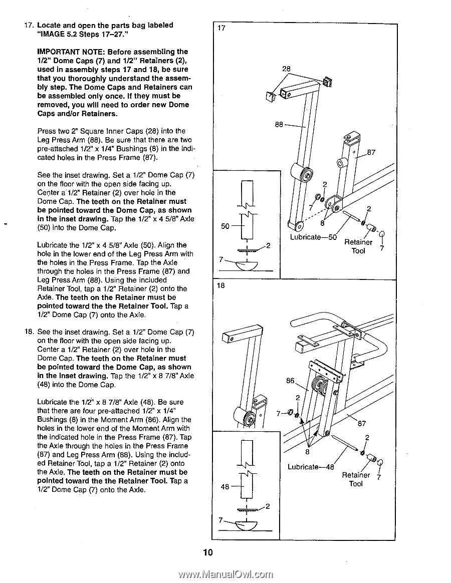
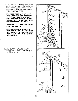
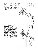
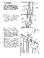
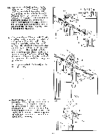
17. Locate and open the parts bag labeled "IMAGE 5.2 Steps 17-27." IMPORTANT NOTE: Before assembling the 1/2" Dome Caps (7) and 1/2" Retainers (2), used in assembly steps 17 and 18, be sure that you thoroughly understand the assembly step. The Dome Caps and Retainers can be assembled only once. If they must be removed, you will need to order new Dome Caps and/or Retainers. Press two 2" Square Inner Caps (28) into the Leg Press Arm (88). Be sure that there are two pre-attached 1/2" x 1/4" Bushings (8) in the indicated holes in the Press Frame (87). See the inset drawing. Set a 1/2" Dome Cap (7) on the floor with the open side facing up. Center a 1/2" Retainer (2) over hole in the Dome Cap. The teeth on the Retaiher must be pointed toward the Dome Cap, as shown in the inset drawing. Tap the 1/2" x 4 5/8" Axle (50) into the Dome Cap. Lubricate the 1/2" x 4 5/8" Axle (50). Align the hole in the lower end of the Leg Press Arm with the holes in the Press Frame. Tap the Axle through the holes in the Press Frame (87) and Leg Press Arm (88). Using the included Retainer Tool, tap a 1/2" Retainer (2) onto the Axle. The teeth on the Retainer must be pointed toward the the Retainer Tool. Tap a 1/2" Dome Cap (7) onto the Axle. 18. See the inset drawing. Set a 1/2" Dome Cap (7) on the floor with the open side facing up. Center a 1/2" Retainer (2) over hole in the Dome Cap. The teeth on the Retainer must be pointed toward the Dome Cap, as shown in the inset drawing. Tap the 1/2" x 8 7/8" Axle (48) into the Dome Cap. Lubricate the 1/2" x 8 7/8" Axle (48). Be sure that there are four pre-attached 1/2" x 1/4" Bushings (8) in the Moment Arm (86). Align the holes in the lower end of the Moment Arm with the indicated hole in the Press Frame (87). Tap the Axle through the holes in the Press Frame (87) and Leg Press Arm (88). Using the included Retainer Tool, tap a 1/2" Retainer (2) onto the Axle. The teeth on the Retainer must be pointed toward the the Retainer Tool. Tap a 1/2" Dome Cap (7) onto the Axle. 17 50 18 0 1 148 28 0 88 O 87 0 7 2 0 8 Lubricate-50 Retainer -? Tool 7 • 86 • 2 7-4) 87 2 8 Lubricate-48 Retainer 7 Tool 10
-
 1
1 -
2
-
3
-
4
-
 5
5 -
 6
6 -
 7
7 -
 8
8 -
 9
9 -
 10
10 -
 11
11 -
 12
12 -
 13
13 -
 14
14 -
 15
15 -
16
-
17
-
18
-
19
-
20
-
21
-
22
-
23
-
24
-
25
-
26
-
27
-
28
-
29
-
30
-
31
-
32
-
33
-
34
-
35
-
36
-
37
-
38
-
39
 |
 |