Image Fitness 5.2 English Manual - Page 17
completely
 |
View all Image Fitness 5.2 manuals
Add to My Manuals
Save this manual to your list of manuals |
Page 17 highlights
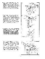
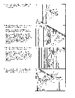
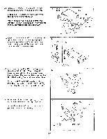
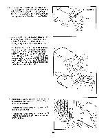
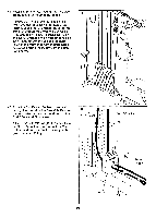
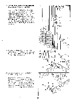
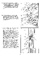
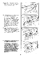
38. Press a 3/4" Round Inner Cap (40) into each end of the pad tube on the Seat Frame (98). Slide a Foam Pad (56) onto each side of the pad tube on the Seat Frame (98). Attach the Seat (63) to the Seat Frame (98) with four 1/4" x 3/4" Screws (24). The wide end of the Seat must be on the side shown. 39. Attach the Seat Frame (98) to the Front Upright (65) with two 3/8" x 5" Bolts (14), a Support Bracket (78), and two 3/8" Nylon Locknuts (1). Note: The long end of the Support Bracket must be facing down as shown. 38 Wide End 24 56 ° 39 78 65 14 , •. • Long ' End ° .. 98 63 56 98 40 , • Pad Tube 40 1 . 40. Attach the Locking Pin (55) to the Leg Lever (99) with a 3/8" Nut (21). The Locking Pin 40 must be inserted from the indicated side of the Leg Lever. Do not completely tighten the Nut. The Locking Pin must be able to rotate. Thread the 3/8" Knob (54) onto the Locking Pin (55). Use a wrench to hold the 3/8" Nut (21) secure. Tighten the Knob against the Nut. 99 55 . 21 . O--54 41. Press a 3/4" Round Inner Cap (40) into each end of the pad tube on the Leg Lever (99). Slide a Foam Pad (56) onto each side of the pad tube on the Leg Lever (99). 41 40 56 vJ 17 99 56 40 Pad Tube
-
 1
1 -
2
-
3
-
4
-
5
-
6
-
7
-
8
-
9
-
10
-
11
-
 12
12 -
 13
13 -
 14
14 -
 15
15 -
 16
16 -
 17
17 -
 18
18 -
 19
19 -
 20
20 -
 21
21 -
 22
22 -
23
-
24
-
25
-
26
-
27
-
28
-
29
-
30
-
31
-
32
-
33
-
34
-
35
-
36
-
37
-
38
-
39
 |
 |
