Image Fitness 5.2 English Manual - Page 23
Image Fitness 5.2 Manual
 |
View all Image Fitness 5.2 manuals
Add to My Manuals
Save this manual to your list of manuals |
Page 23 highlights
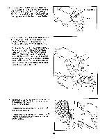
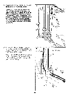
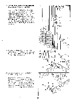
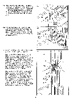
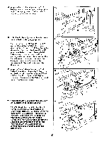
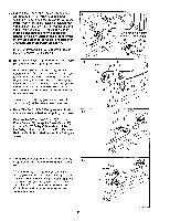
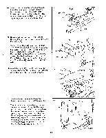
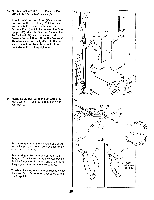
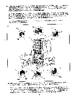
57. See the inset drawing. Wrap the Press Cable (95) around a 3 1/2" Pulley (30) as shown. Attach the Pulley and a Pulley Cover (23) to the Press Frame (87) in the indicated location with a 3/8" x 3 3/4" Bolt (16), a 3/8" Washer (5), and a 3/8" Nylon Locknut (1). The Pulley Cover must be oriented as shown and be positioned to hold the Cable in the groove of the Pulley. Be sure that the Cable is routed over and then under the Pulley as shown. Route the Press Cable (95) under the tube on the Moment Arm (86) as shown. 58. Note: The Pulleys (30) used in this step were pre-attached for shipping purposes. Remove the 3/8" x 4 3/4" Bolt (12), the 3/8" Nylon Jam Nut (20), and the two 3 1/2" Pulleys (30) from the Leg Press Arm (88). Wrap the Press Cable (95) around one of the Pulleys as shown. Re-attach the Pulley to indicated side of the Press Frame with the Bolt. Be sure that the Cable is routed under and then over the Pulley as shown. The other 3 1/2" Pulley (30) and the 3/8" Nylon Jam Nut (20) will be re-attached in step 60. 59. Note: The 3/8" x 1 3/4" Bolt (10) used in this step was pre-attached for shipping purposes. Remove the 3/8" x 1 3/4" Bolt (10) from the Press Frame (87). Wrap the Press Cable (95) around a 3 1/2" Pulley (30) as shown. Attach the Pulley to the bracket with the Bolt. Be sure that the Cable is routed around the Pulley as shown. 60. Note: The Pulley (30) and the Nylon Locknut (20) used in this step were removed in step 58. Wrap the Press Cable (95) around the 3 1/2" Pulley (30) that was removed in step 58. Slide the Pulley onto the 3/8" x 4 3/4" Bolt (12) in the Leg Press Arm (88). Re-attach the 3/8" Nylon Jam Nut (20) to the Bolt. Be sure that the Cable is routed over and then under the Pulley as shown. 57 _--- O. 86 Tube 95 58 12 Inset shows view from . 87 other side of upright 30 1 23 ,. ---16 -----.5 95 87 95 l @/ 30 8 a o 30 20 izi 59 III tr--1U s \, 1 1 6* 30 ._ . 95 87 60 88 12 g 30 9 5 2 23
-
 1
1 -
2
-
3
-
4
-
5
-
6
-
7
-
8
-
9
-
10
-
11
-
12
-
13
-
14
-
15
-
16
-
17
-
 18
18 -
 19
19 -
 20
20 -
 21
21 -
 22
22 -
 23
23 -
 24
24 -
 25
25 -
 26
26 -
 27
27 -
 28
28 -
29
-
30
-
31
-
32
-
33
-
34
-
35
-
36
-
37
-
38
-
39
 |
 |
