Image Fitness 5.2 English Manual - Page 5
Stabilizer
 |
View all Image Fitness 5.2 manuals
Add to My Manuals
Save this manual to your list of manuals |
Page 5 highlights
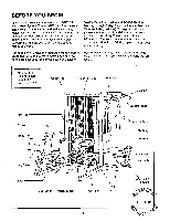
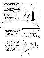
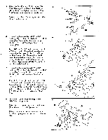
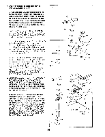
2. Align the holes in the bracket on the Base (94) with the holes in the Press Frame (87). Turn the Front and Rear Uprights (65, 77) and the Top Frame (not shown) right side up. Slide the Rear Upright onto the Press Frame (87) and slide the Front Upright onto the Base (94) as shown. Attach the Front Upright to the Base with two 3/8" x 4 3/4" Bolts (12), two 3/8" Washers (5), and two 3/8" Nylon Locknuts (1). The Bolts and Washers must be on the side shown. Tighten the Nylon Locknuts. Press a 2" x 3" Inner Cap (52) into the end of the Base (94). Attach four Lower Shield Brackets (119) to the Base (94) with eight 1/2" Self-tapping Screws (118). The Brackets must be oriented as shown. Note: The Self-tapping Screws will require some effort to thread into place. 2 77 118 87 0 Bracket 119 65 5 12 5 3. Attach the Rear Upright (77) and the Base (94) to the PfeSS Frame (07) with four 310" x Dolts 3 (11) and four 3/8" Nylon Locknuts (1) as shown. Do not tighten the Nylon Locknuts yet. Press a 2" Square Inner Cap (28) into the Press Frame (87). Press a 2" x 3" Inner Cap (52) into the end of the Press Frame. 28 94 52 11 87 77 52 0 94 ett 4. Press a 2" x 3" Inner Cap (52) into the end of the Stabilizer (112). Be sure that the Stabilizer is turned so the indicated hole is up. Insert two 3/8" x 3 3/4" Carriage Bolts (110) up through the holes in the Stabilizer (112). Attach the Stabilizer (112) to the Base (94) with four 3/8" x 3" Bolts (11), four 3/8" Washers (5), and four 3/8" Nylon Locknuts (1). Do not tighten the Nylon Locknuts yet. 4 Hole 52 112 110 5 5 11 5 94
-
 1
1 -
 2
2 -
 3
3 -
 4
4 -
 5
5 -
 6
6 -
 7
7 -
 8
8 -
 9
9 -
 10
10 -
 11
11 -
12
-
13
-
14
-
15
-
16
-
17
-
18
-
19
-
20
-
21
-
22
-
23
-
24
-
25
-
26
-
27
-
28
-
29
-
30
-
31
-
32
-
33
-
34
-
35
-
36
-
37
-
38
-
39
 |
 |
