Image Fitness 5.2 English Manual - Page 4
Assembly
 |
View all Image Fitness 5.2 manuals
Add to My Manuals
Save this manual to your list of manuals |
Page 4 highlights
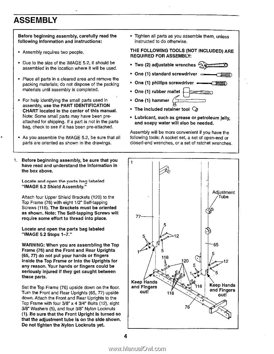
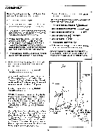
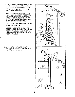
ASSEMBLY Before beginning assembly, carefully read the following information and instructions: • Assembly requires two people. • Due to the size of the IMAGE 5.2, it should be assembled in the location where it will be used. • Place all parts in a cleared area and remove the packing materials; do not dispose of the packing materials until assembly is completed. • For help identifying the small parts used in assembly, use the PART IDENTIFICATION CHART located in the center of this manual. Note: Some small parts may have been preattached for shipping. If a part is not in the parts bag, check to see if it has been pre-attached. • As you assemble the IMAGE 5.2, be sure that all parts are oriented as shown in the drawings. • Tighten all parts as you assemble them, unless instructed to do otherwise. THE FOLLOWING TOOLS -(NOT INCLUDED) ARE REQUIRED FOR ASSEMBLY: • Two (2) adjustable wrenches • One (1) standard screwdriver • One (1) phIllips screwdriver • One (1) rubber mallet Cam) • One (1) hammer • The included retainer tool Cb • Lubricant, such as grease or petroleum jelly, and soapy water will also be needed. Assembly will be more convenient if you have the following tools: A socket set, a set of open-end or closed-end wrenches, or a set of ratchet wrenches. 1. Before beginning assembly, be sure that you 1 have read and understand the information in the box above. Locate and npPn thP paric hag lahPIPci "IMAGE 5.2 Shield Assembly." Attach four Upper Shield Brackets (120) to the Top Frame (76) with eight 1/2" Self-tapping Screws (118). The Brackets must be oriented as shown. Note: The Self-tapping Screws will require some effort to thread into place. Locate and open the parts bag labeled "IMAGE 5.2 Steps 1-7." WARNING: When you are assembling the Top Frame (76) and the Front and Rear Uprights (65, 77) do not put your hands or fingers inside the Top Frame or into the Uprights for any reason. Your hands or fingers could be seriously injured if they get caught between these parts. Set the Top Frame (76) upside down on the floor. Turn the Front and Rear Uprights (65, 77) upside down. Attach the Front and Rear Uprights to the Top Frame with four 3/8" x 4 3/4" Bolts (12), eight 3/8" Washers (5), and four 3/8" Nylon Locknuts (1). Be sure that the Front Upright is turned so that the adjustment tube is on the side shown. Do not tighten the Nylon Locknuts yet. Adjustment Tube 77 5 5 • 12 65 5 5 118 120 5 Keep Hands and Fingers out! 118 118 Keep Hands and Fingers out! 76 4
-
 1
1 -
 2
2 -
 3
3 -
 4
4 -
 5
5 -
 6
6 -
 7
7 -
 8
8 -
 9
9 -
 10
10 -
11
-
12
-
13
-
14
-
15
-
16
-
17
-
18
-
19
-
20
-
21
-
22
-
23
-
24
-
25
-
26
-
27
-
28
-
29
-
30
-
31
-
32
-
33
-
34
-
35
-
36
-
37
-
38
-
39
 |
 |