Image Fitness 5.2 English Manual - Page 6
another
 |
View all Image Fitness 5.2 manuals
Add to My Manuals
Save this manual to your list of manuals |
Page 6 highlights
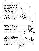
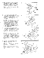
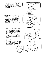
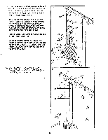
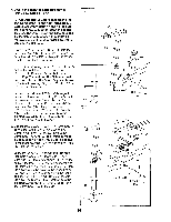
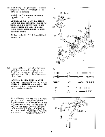
5. Attach the Curl Frame (109) to the two 3/8" x 5 3 3/4" Carriage Bolts (110) in the Stabilizer (112) with two 3/8" Nylon Locknuts (1). The Curl Frame must be oriented as shown. Press a 1" x 3" Inner Cap (117) into each side of the Curl Frame (109). 117 . . . . a-117 . : 109 6. Be sure that the pre-attached 1/2" x 1.7" Bushing (35) is in the indicated hole in the Curl Lever (114). Be sure that there are two preattached 1/2" x 1/4" Bushings (8) in the Curl Frame (109). Tap a 1/2" Hat Cap (47) onto one end of a 1/2" x 3" Axle (111). Lubricate the Axle. Align the holes in the Curl Lever (114) with the holes in the Curl Frame (109). Be sure that the Curl Lever is oriented as shown. Tap the Axle through the holes in the Curl Frame and the Curl Lever. Tap another 1/2" Hat Cap (47) onto the other end of the Axle. 7. Be sure that the pre-attached 1/2" x 1.7" Bushing (35) is I ever (114). 00 isnutrhee♦thinadtictraaterad hole in are 'laic the Curl p1 G' 1/2" x 1/4" Bushings (8) in the Curl Bar (113). Tap a 1/2" Hat Cap (47) onto one end of a 1/2" x 3" Axle (111). Lubricate the Axle. Align the holes in the Curl Bar (113) with the holes in the Curl Lever (114). Tap the Axle through the holes in the Curl Bar and the Curl Lever. Tap another 1/2" Hat Cap (47) onto the other end of the Axle. 8. Locate and open the parts bag labeled "IMAGE 5.2 Steps 8-16." Attach the Chest Pad (18) to the Curl Frame (109) with two 1/4" x 3/4" Screws (24). Attach an Arm Pad (116) to each side of the Curl Frame (109) with two 1/4" x 1 1/2" Screws (115). 1 • 112 110 6 111 47---g. 8 109 .-- , . • 114 47 35 CVi 114 . * 47 8 35 113 47 111 8 116 109 2 115 ': c. ,.. .• 18 116 • ,• 2 ---„,, . ..... 115 -,, 6
-
 1
1 -
 2
2 -
 3
3 -
 4
4 -
 5
5 -
 6
6 -
 7
7 -
 8
8 -
 9
9 -
 10
10 -
 11
11 -
 12
12 -
13
-
14
-
15
-
16
-
17
-
18
-
19
-
20
-
21
-
22
-
23
-
24
-
25
-
26
-
27
-
28
-
29
-
30
-
31
-
32
-
33
-
34
-
35
-
36
-
37
-
38
-
39
 |
 |
