Intel Q9450 Design Guidelines
Intel Q9450 - Core 2 Quad Quad-Core Processor Manual
 |
UPC - 735858198493
View all Intel Q9450 manuals
Add to My Manuals
Save this manual to your list of manuals |
Intel Q9450 manual content summary:
- Intel Q9450 | Design Guidelines - Page 1
Intel® Core™2 Extreme QuadCore Processor and Intel® Core™2 Quad Processor Thermal and Mechanical Design Guidelines Supporting: Intel® Core™2 Extreme quad-core processor QX6000Δ series at 775_VR_CONFIG_05B Intel® Core™2 Quad processor Q6000Δ series at 105 W Intel® Core™2 Quad processor Q6000Δ - Intel Q9450 | Design Guidelines - Page 2
, Intel® Core™2 Extreme Processor QX9000 series Intel® Core™2 Quad processor Q9000, Q9000S, Q8000, and Q8000S series and Intel® Core™2 Quad processor Q6000 Δ series may contain design defects or errors known as errata, which may cause the product to deviate from published specifications. Current - Intel Q9450 | Design Guidelines - Page 3
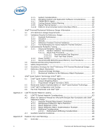
Thermal Solution Performance Assessment 31 3.3 Local Ambient Temperature Measurement Guidelines 32 3.4 Processor Case Temperature Measurement Guidelines 34 4 Thermal Management Logic and Thermal Monitor Feature 35 4.1 Processor Power Dissipation 35 4.2 Thermal Monitor Implementation 35 - Intel Q9450 | Design Guidelines - Page 4
Fan Hub Thermistor and Intel® QST 62 LGA775 Socket Heatsink Loading 63 A.1 LGA775 Socket Heatsink Considerations 63 A.2 Metric for Heatsink Preload for ATX/uATX Designs Non-Compliant with Intel® Reference Design 63 A.2.1 Heatsink Preload Requirement Limitations 63 A.2.2 Motherboard Deflection - Intel Q9450 | Design Guidelines - Page 5
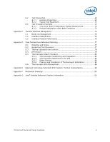
Examples 72 B.3.1 Time-Zero, Room Temperature Preload Measurement 73 B.3.2 Preload Degradation under 75 Case Temperature Reference Metrology 77 D.1 Objective and Scope 77 D.2 Supporting Test Equipment Cleaning and Completion of Thermocouple Installation 93 D.6 Thermocouple Wire - Intel Q9450 | Design Guidelines - Page 6
33 Figure 6. Locations for Measuring Local Ambient Temperature, Passive Heatsink ......33 Figure 7. Thermal Monitor Control 37 Figure 8. Thermal Monitor 2 Frequency and Voltage Ordering 38 Figure 9. TCONTROL for Digital Thermometer 41 Figure 10. Intel® RCFH-4 Reference Design - Exploded View 43 - Intel Q9450 | Design Guidelines - Page 7
54. Finished Thermocouple Installation 96 Figure 55. 60. ATX/µATX Motherboard Keep-out Footprint Definition Intel® RCFH4 Reference Solution Assembly 118 Figure 73. Intel® RCFH4 Reference Solution Assembly - Page 2 119 Figure 74. Intel® D60188-001 Reference Solution Assembly 120 Figure 75. Intel - Intel Q9450 | Design Guidelines - Page 8
Tables Table 1. Heatsink Inlet Temperature of Intel Reference Thermal Solutions 27 Table 2. Heatsink Inlet Temperature of Intel® Boxed Processor thermal solutions .....27 Table 3. ATX Reference Heatsink Performance (RCFH-4) for 775_VR_CONFIG 05B Processors 45 Table 4. ATX Reference Heatsink - Intel Q9450 | Design Guidelines - Page 9
Removed Legacy Fan Speed Control appendix. Added Intel® Core™2 Quad processors Q9550, Q9450, and Q9300 Added Intel® Core™2 Quad processors Q9650 and Q9400 Added Intel® Core™2 Quad processors Q8200 Added Intel® Core™2 Quad processors Q8300 Added Intel® Core™2 Quad processor Q9000S and - Intel Q9450 | Design Guidelines - Page 10
10 Thermal and Mechanical Design Guidelines - Intel Q9450 | Design Guidelines - Page 11
the Intel® Core™2 Extreme quad-core processor QX6000 series, Intel® Core™2 Quad processor Q6000 series, Intel® Core™2 Quad processor Q9000 and Q8000series, and Intel® Core™2 Extreme processor QX9650. The concepts given in this document are applicable to any system form factor. Specific examples - Intel Q9450 | Design Guidelines - Page 12
Intel® Core™2 Quad processors Q9650, Q9550, Q9505, Q9450, 9400, and Q9300 Intel® Core™2 Quad processor Q8000 series at 95 W applies to the Intel® Core™2 Quad processors Q8200, Q8300, and Q8400 Intel® Core™2 Quad processor Q9000S series at 65 W applies to the Intel® Core™2 Quad processors Q9550S - Intel Q9450 | Design Guidelines - Page 13
Series and Intel® Core™2 Quad Processor Q9000, Q9000S, Q8000, and Q8000SSeries Datasheet Intel® Core™2 Duo Processor E8000 and E7000 Series and Intel® Pentium® Dual-Core Processor E5000 Series Thermal and Mechanical Design Guide LGA775 Socket Mechanical Design Guide Fan Specification for 4-wire - Intel Q9450 | Design Guidelines - Page 14
through heat spreading. The surface mount socket designed to accept the processors in the 775- Land LGA package. The maximum power dissipated by a semiconductor component. Pulse width modulation is a method of controlling a variable speed fan. The enabled 4 wire fans use the PWM duty cycle % from - Intel Q9450 | Design Guidelines - Page 15
Monitor TIM TMA TS CA CS SA Description A feature on the processor that attempts to keep the processor die temperature within factory specifications. Thermal Interface Material: The thermally conductive compound between the heatsink and the processor case. This material fills the air gaps and - Intel Q9450 | Design Guidelines - Page 16
Introduction 16 Thermal and Mechanical Design Guidelines - Intel Q9450 | Design Guidelines - Page 17
775-Land LGA package that interfaces with the motherboard via a LGA775 socket. Refer to the datasheet for detailed mechanical specifications. The processor connects to the motherboard through a land grid array (LGA) surface mount socket. The socket contains 775 contacts arrayed about a cavity in the - Intel Q9450 | Design Guidelines - Page 18
heatsink. The IHS also features a step that interfaces with the LGA775 socket load plate, as described in LGA775 Socket Mechanical Design Guide. The load from the load the IHS, it should not exceed the corresponding specification given in the processor datasheet. When a compressive static load is - Intel Q9450 | Design Guidelines - Page 19
and vibration is constrained by the LGA775 socket load plate (refer to the LGA775 Socket Mechanical Design Guide for further information). 2.1.2.2 Heatsink Clip Load Requirement The attach mechanism for the heatsink developed to support the processor should create a static preload on the package - Intel Q9450 | Design Guidelines - Page 20
and into the socket is usually minimal. The thermal limits for the processor are the Thermal Profile and TCONTROL. The Thermal Profile defines the maximum case temperature as a function of power being dissipated. TCONTROL is a specification used in conjunction with the temperature reported by the - Intel Q9450 | Design Guidelines - Page 21
will have up to a 35 °C ambient temperature external to the system. For ATX platforms using the Intel® Core™2 Extreme quad-core processor QX6000 series at the 775_CONFIG_05B, an active air-cooled design in a Thermally Advantaged Chassis, with a fan installed at the top of the heatsink equivalent to - Intel Q9450 | Design Guidelines - Page 22
the Intel® Core™2 Quad processor Q6000 series at 95 W, an active air-cooled design, assumed be used in ATX Chassis, with a fan installed at the top of the heatsink equivalent to the D60188-001 reference design (see Chapter 5) should be designed to manage the processor TDP at an inlet temperature of - Intel Q9450 | Design Guidelines - Page 23
TCONTROL TCONTROL defines the maximum operating temperature for the digital thermal sensor when the thermal solution fan speed is being controlled by the digital thermal sensor. The TCONTROL parameter defines a very specific processor operating region where fan speed can be reduced. This allows - Intel Q9450 | Design Guidelines - Page 24
processor datasheet for further details on reading the register and calculating TCONTROL. See Chapter 6 Intel® Quiet System Technology (Intel . It is characterized by the local ambient temperature of the air, TA, and the local Active heatsinks typically incorporate a fan that helps manage the airflow - Intel Q9450 | Design Guidelines - Page 25
socket in Appendix F of this design guide. The motherboard primary side height constraints defined in the ATX Specification V2.2 and the microATX Motherboard Interface Specification ATX thermal solution is 550 g. This mass includes the fan and the heatsink only. The attach mechanism (clip, - Intel Q9450 | Design Guidelines - Page 26
Processor Thermal/Mechanical Information reviewed in depth in the Balanced Technology Extended (BTX) System Design Guide v1.0. Note: The 550g mass limit for ATX solutions is based on the capabilities of the reference design components that retain the heatsink to the - Intel Q9450 | Design Guidelines - Page 27
Temperature of Intel® Boxed Processor thermal solutions Type Boxed Processor Heatsink for Intel® Core™2 Extreme quad-core processor QX6000 series at the 775_VR_CONFIG_05B, Intel® Core™2 Quad processor Q6000 series, Intel® Core™2 Extreme processor QX9000 series, and Intel® Core™2 Quad processor - Intel Q9450 | Design Guidelines - Page 28
all aspects LGA775 socket based platforms and systems manufacturing. Of particular interest for package and heatsink installation and removal is the System Assembly module. A video covering system integration is also available. Contact your Intel field sales representative for further information - Intel Q9450 | Design Guidelines - Page 29
TC TA PD = Case-to-local ambient thermal characterization parameter (°C/W) = Processor case temperature (°C) = Local ambient temperature in chassis at processor (°C) = Processor total power dissipation (W) (assumes all power dissipates through the IHS) Thermal and Mechanical Design Guidelines 29 - Intel Q9450 | Design Guidelines - Page 30
the fins of the heatsink. Figure 4 illustrates the combination of the different thermal characterization parameters. Figure 4. Processor Thermal Characterization Parameter Relationships TA Heatsink TIM IHS Processor CA TS TC LGA775 Socket System Board 30 Thermal and Mechanical Design Guidelines - Intel Q9450 | Design Guidelines - Page 31
provides an illustration of how one might determine the appropriate performance targets. The example power and temperature numbers used here are not related to any specific Intel processor thermal specifications, and are for illustrative purposes only. Assume the TDP, as listed in the datasheet - Intel Q9450 | Design Guidelines - Page 32
useful to add a thermocouple taped to the barrier above the location of the temperature sensor used by the fan to check its speed setting against air temperature. When measuring TA in a chassis with a live motherboard, add-in cards, and other system components, it is likely that the TA measurements - Intel Q9450 | Design Guidelines - Page 33
Thermal Metrology Figure 5. Locations for Measuring Local Ambient Temperature, Active Heatsink NOTE: Drawing Not to Scale Figure 6. Locations for Measuring Local Ambient Temperature, Passive Heatsink NOTE: Drawing Not to Scale Thermal and Mechanical Design Guidelines 33 - Intel Q9450 | Design Guidelines - Page 34
known standards. When measuring the temperature of a surface that is at a different temperature from the surrounding local ambient air Land LGA processor package for TC measurement. This procedure takes into account the specific features of the 775-Land LGA package and of the LGA775 socket for - Intel Q9450 | Design Guidelines - Page 35
reduce processor power consumption. An on-die thermal management feature called Thermal Monitor is available on the processor. It provides a thermal management approach to support the continued increases in processor frequency and performance. By using a highly accurate on-die temperature sensing - Intel Q9450 | Design Guidelines - Page 36
Control Circuit portion of the Thermal Monitor must be enabled for the processor to operate within specifications. The Thermal Monitor's TCC, when active, will attempt to lower the processor temperature by reducing the processor power consumption. There are two methods by which TCC can reduce - Intel Q9450 | Design Guidelines - Page 37
bus-to-core multiplier to its minimum available value) and input voltage identification (VID) value. This combination of reduced frequency and VID results in a reduction in processor power consumption. A processor enabled for TM2 includes two operating points, each consisting of a specific operating - Intel Q9450 | Design Guidelines - Page 38
(model specific register). Enabling the Thermal Control Circuit allows the processor to attempt to maintain a safe operating temperature without the need for special software drivers or interrupt handling routines. When the Thermal Control Circuit has been enabled, processor power consumption will - Intel Q9450 | Design Guidelines - Page 39
processor. The power reduction mechanism of thermal monitor can also be activated manually using an "on-demand" mode. Refer to Section 4.2.4 for details on this feature. 4.2.4 On-Demand Mode For testing purposes, the thermal control circuit may also be activated by setting high temperature - Intel Q9450 | Design Guidelines - Page 40
that the Thermal Monitor feature will not be capable of reducing the processor power and temperature and the processor could shutdown and signal THERMTRIP#. For information regarding THERMTRIP#, refer to the processor datasheet and to Section 4.2.7 of this thermal design guide. Operating System and - Intel Q9450 | Design Guidelines - Page 41
device. Figure 9. TCONTROL for Digital Thermometer Thermal Diode Temperature Digital Thermometer Temperature Tcontrol= 66 Tcontrol= -10 70 0 60 20 50 Temperature 30 40 Power 40 30 50 20 Fan Speed 60 10 70 Time Note: The processor does not have an on-die thermal diode. The - Intel Q9450 | Design Guidelines - Page 42
only data being transmitted. For an overview of the PECI interface see PECI Feature Set Overview. For additional information on the PECI, see the Datasheet. The PECI bus is available on pin G5 of the LGA 775 socket. Intel chipsets beginning with the ICH8 have included PECI host controller. The PECI - Intel Q9450 | Design Guidelines - Page 43
active air-cooled design, with a fan installed at the top of the heatsink. The thermal technology required for the processor. The Intel® Core™2 Extreme quad-core processor QX6000 series at the 775_VR_CONFIG_05B and Intel® Core™2 Extreme processor QX9000 series require a thermal solution equivalent - Intel Q9450 | Design Guidelines - Page 44
of an acoustic improvement to reduce the fan speed to show the acoustic advantage (its acoustic results are shown in the Table 6). Note: If the heatsink design is used in the Intel® Core™2 Quad processor Q6000 series at 95 W and Intel® Core™2 Quad processor Q9000 and Q8000 series at 95 W for - Intel Q9450 | Design Guidelines - Page 45
energized fan by the user during user servicing. 5.2 Validation Results for Reference Design 5.2.1 Heatsink Performance Table 3 provides the RCFH-4 heatsink performance for the 775_VR_CONFIG 05B processors. Table 4 provides the D60188-001 heatsink performance for the Intel® Core™2 Quad processor - Intel Q9450 | Design Guidelines - Page 46
Intel® Core™2 Quad processor Q9000 and Q8000 series at 95 W Target Thermal Performance, ca (Mean + 3) 0.33 C/W TA Assumption TA = 40 C NOTES: 1. Performance targets (Ψ ca) as measured with a live processor at TDP. Notes 1 5.2.2 Acoustics To optimize acoustic emission by the fan heatsink - Intel Q9450 | Design Guidelines - Page 47
, additional acoustic improvements can be achieved at lower processor workload by using the TCONTROL specifications described in Section 2.2.3. Intel recommendation is to use the Fan Specification for 4 Wire PWM Controlled Fans to implement fan speed control capability based on the digital thermal - Intel Q9450 | Design Guidelines - Page 48
must demonstrate adequate performance after 7,500 on/off cycles with each cycle specified as 3 minutes on, 2 minutes off, at a temperature of 70 °C. See the Fan Specification for 4-wire PWM Controlled Fans for additional details on the fan specification. 48 Thermal and Mechanical Design Guidelines - Intel Q9450 | Design Guidelines - Page 49
Intel Duration: 10 min/axis, 3 axes Frequency Range: 5 Hz to 500 Hz Power Spectral Density (PSD) Profile: 3.13 G RMS Figure 13. Random Vibration PSD 500 Hz 1000 5.3.1.2 Shock Test Procedure Recommended performance requirement for a motherboard: Quantity: 3 drops for + and - directions in each - Intel Q9450 | Design Guidelines - Page 50
Intel® Thermal/ motherboard surface due to impact of heatsink or heatsink attach mechanism. 5. No visible physical damage to the processor package. 6. Successful BIOS/Processor/memory test of post-test samples. 7. Thermal compliance testing to demonstrate that the case temperature specification - Intel Q9450 | Design Guidelines - Page 51
setup should include the following components, properly assembled and/or connected: Appropriate system motherboard Processor All enabling components, including socket and thermal solution parts Power supply Disk drive Video card DIMM Keyboard Monitor The pass criterion is that - Intel Q9450 | Design Guidelines - Page 52
the moving parts of the fan, consider adding safety feature so that there is no risk of personal injury. Geometric Envelope for Intel® Reference ATX Thermal Mechanical Design Figure 58, Figure 59 and Figure 60 in Appendix F gives detailed reference ATX/μATX motherboard keep-out information for the - Intel Q9450 | Design Guidelines - Page 53
Intel® Thermal/Mechanical Reference Design Information 5.7 Reference Attach Mechanism 5.7.1 Structural Design Strategy Structural design strategy for the reference design is to minimize upward board deflection during shock to help protect the LGA775 socket. The reference design uses a high clip - Intel Q9450 | Design Guidelines - Page 54
Intel® attach mechanism consists of: A metal attach clip that interfaces with the heatsink core, see Appendix F Figure 66 and Figure 67 for the component drawings. reference attach mechanism (clip and fasteners) include: Heatsink/fan mass ≤ 550 g (i.e., total assembly mass, including clip and - Intel Q9450 | Design Guidelines - Page 55
Clip Fan Fin Array Core See Detail A Clip Fin Array Clip 1.6 mm Core Detail A Figure 18. Critical Core Dimension 1.00 +/- 0.10 mm 1.00 mm min 38.68 +/- 0.30 mm 36.14 +/- 0.10 mm Gap required to avoid core surface blemish during clip assembly. Recommend 0.3 mm min. Core R 0.40 mm max - Intel Q9450 | Design Guidelines - Page 56
Intel® Thermal/Mechanical Reference Design Information 56 Thermal and Mechanical Design Guidelines - Intel Q9450 | Design Guidelines - Page 57
Weighting Matrix uses the effects of each fan on a thermal sensor to minimize the required fan speed changes Figure 19 shows in a very simple manner how Intel QST works. See the Intel® Quiet System Technology (Intel® QST) Configuration and Tuning Manual for a detail discussion of the inputs and - Intel Q9450 | Design Guidelines - Page 58
processor heatsink fan and a 2nd fan in the system. By placing a factor in this matrix additional the Intel QST could command the processor thermal solution fan and this 2nd fan fan response to be determined based upon the difference between current temperature readings and specific temperature - Intel Q9450 | Design Guidelines - Page 59
Integral (time averaged) Actual Temperature Proportional Error Limit Temperature Derivative (Slope) + dPWM Time Fan Speed RPM For a PID algorithm to work, limit temperatures are assigned for each temperature sensor. For Intel QST, the TCONTROL for the processor and chipset are to be - Intel Q9450 | Design Guidelines - Page 60
in Figure 21 and listed below: ME system (S0-S1) with Controller Link connected and powered DRAM with Channel A DIMM 0 installed and 2 MB reserved for Intel QST FW execution SPI Flash with sufficient space for the Intel QST Firmware SST-based thermal sensors to provide board thermal data for - Intel Q9450 | Design Guidelines - Page 61
for the processor socket. Additional SST sensors can be added to monitor system thermal (see Appendix E for BTX recommendations for placement). Figure 22. Example Acoustic Fan Speed Control Implementation Intel has engaged with a number of major manufacturers of thermal / voltage sensors to provide - Intel Q9450 | Design Guidelines - Page 62
and Tuning Initial configuration of the Intel QST is the responsibility of the board manufacturer. The SPI flash should be programmed with the hardware configuration of the motherboard and initial settings for fan control, fan monitoring, voltage and thermal monitoring. This initial data - Intel Q9450 | Design Guidelines - Page 63
tensile stress is originally created when, after inserting a processor into the socket, the LGA775 socket load plate is actuated. In addition, solder joint shear LGA775 socket protection against fatigue failure. Metric for Heatsink Preload for ATX/uATX Designs Non-Compliant with Intel® Reference - Intel Q9450 | Design Guidelines - Page 64
socket diagonal. The matching of Faxial required to protect the LGA775 socket solder joint in temperature ATX//µATX form factor. A.2.2 Motherboard Deflection Metric Definition Motherboard deflection is measured along either Configuration Parameter d_ref Processor + Socket load plate yes Heatsink - Intel Q9450 | Design Guidelines - Page 65
LGA775 Socket Heatsink Loading Figure 24. Board Deflection Definition d1 d'1 d2 must remain within the static load limits defined in the processor datasheet at all times. 2. Board deflection should not exceed motherboard manufacturer specifications. Thermal and Mechanical Design Guidelines 65 - Intel Q9450 | Design Guidelines - Page 66
Socket with selected material and board manufacturing process. Check with your motherboard vendor. Clip stiffness assumed board deflection as the motherboard creeps under exposure to time and temperature. In contrast, end of life board deflection. 66 Thermal and Mechanical Design Guidelines - Intel Q9450 | Design Guidelines - Page 67
LGA775 Socket Heatsink Loading Figure 25. Example: Defining Heatsink Preload Meeting Board Deflection Limit A.2.5 Additional Considerations Intel recommends to (Refer to processor datasheet) 2. Board deflection should not exceed motherboard manufacturer specifications. Thermal and Mechanical Design - Intel Q9450 | Design Guidelines - Page 68
(RCFH-4, RCBFH-3 and D60188-001) Intel will collaborate with vendors participating in its third party test house program to evaluate third party solutions. Vendor information is available in Intel® Core™2 Quad Processor Support Components webpage www.intel.com/go/thermal_Core2Quad. § 68 Thermal - Intel Q9450 | Design Guidelines - Page 69
socket Quantify preload degradation under bake conditions. Note: This document reflects the current metrology used by Intel. Intel is cell to maintain the load cells in place during the heatsink installation on the processor and motherboard (Refer to Figure 27). The depth of the pocket depends - Intel Q9450 | Design Guidelines - Page 70
height of the heatsink assembly should be preserved. This should not affect the stiffness of the heatsink significantly. Figure 26. Load Cell Installation in Machined Heatsink Base Pocket (Bottom View) Heatsink Base Pocket Diameter ~ 29 mm [~1.15"] Package IHS Outline (Top Surface) Load Cells 70 - Intel Q9450 | Design Guidelines - Page 71
Machined Heatsink Base Pocket (Side View) Height of pocket ~ height of selected load cell Wax to maintain load cell in position during heatsink installation Load cell protrusion (Note: to be optimized depending on assembly stiffness) Figure 28. Preload Test Configuration Preload Fixture (copper - Intel Q9450 | Design Guidelines - Page 72
It is usually better, whenever possible, to operate in the high end of the load cell capability. Check with your load cell vendor into the load cell's wiring) is also placed in the temperature chamber. The load cells can handle up to 121 °C instructions. 72 Thermal and Mechanical Design Guidelines - Intel Q9450 | Design Guidelines - Page 73
Install relevant test vehicle (TTV, processor) in the socket 3. Assemble the heatsink reworked with the load cells to motherboard reading should be taken at the end of this settling time. 5. Record Remove assembly from thermal chamber and set into room temperature conditions 6. Record continuous load - Intel Q9450 | Design Guidelines - Page 74
Heatsink Clip Load Metrology 74 Thermal and Mechanical Design Guidelines - Intel Q9450 | Design Guidelines - Page 75
of factors related to the interface between the processor and the heatsink base. Specifically, the bond line thickness, interface material area and resistance, the larger the temperature drop is across the interface and the more efficient the thermal solution (heatsink, fan) must be to achieve - Intel Q9450 | Design Guidelines - Page 76
Thermal Interface Management § 76 Thermal and Mechanical Design Guidelines - Intel Q9450 | Design Guidelines - Page 77
package for TC measurement. This procedure takes into account the specific features of the 775-land LGA package and of the LGA775 socket for which it is intended. The recommended equipment for the reference thermocouple installation, including tools and part numbers are also provided. In addition - Intel Q9450 | Design Guidelines - Page 78
of temperature measurement equipment be performed before attempting to perform case temperature measurements. Intel recommends checking the meter probe set against handling. 2. Ask your Intel field sales representative if you need assistance to groove and/or install a thermocouple according to the - Intel Q9450 | Design Guidelines - Page 79
. The groove orientation in Figure 30 is toward the IHS notch to allow the thermocouple wire to be routed under the socket lid. This will protect the thermocouple from getting damaged or pinched when removing and installing the heatsink (see Figure 55). Thermal and Mechanical Design Guidelines 79 - Intel Q9450 | Design Guidelines - Page 80
Case Temperature Reference Metrology Figure 30. 775-LAND LGA Package Reference Groove Drawing at 6 o'clock Exit 80 Thermal and Mechanical Design Guidelines - Intel Q9450 | Design Guidelines - Page 81
Case Temperature Reference Metrology Figure 31. 775-LAND LGA Package Reference Groove Drawing at 3 o'clock Exit (Old Drawing) Thermal and Mechanical Design Guidelines 81 - Intel Q9450 | Design Guidelines - Page 82
- Intel Q9450 | Design Guidelines - Page 83
processor is installed in the LGA775 socket, the groove is parallel to the socket socket load. A larger groove may cause the IHS to warp under the socket load such that it does not represent the performance of an ungrooved IHS on production packages. Inspect parts for compliance to specifications - Intel Q9450 | Design Guidelines - Page 84
to 30 minutes to reach the target temperature of 153 - 155 °C. Note: To avoid damage to the TTV or processor ensure the IHS temperature does not exceed 155 °C. As a insulation should be about 1/16 inch (0.062 ± 0.030) from the end of the bead (see Figure 34). Figure 34. Inspection of Insulation - Intel Q9450 | Design Guidelines - Page 85
Case Temperature Reference Metrology Figure 35. Bending the Tip of the Thermocouple D.5.2 Thermocouple wire inside the groove; letting the exposed wire and bead extend about 1.5 mm [0.030 inch] past the end of groove. Secure it with Kapton* tape (see Figure 36). Clean the IHS with a swab and IPA - Intel Q9450 | Design Guidelines - Page 86
tip is in contact with the end and bottom of the groove in the IHS (see Figure 37-A and B). Figure 37. Thermocouple Bead Placement (A) (B) 10. Place the package under the microscope to continue with process. It is also recommended to use a fixture (like processor tray or a plate) to help holding - Intel Q9450 | Design Guidelines - Page 87
Case Temperature Reference Metrology 11. While still at the microscope, press the wire down about 6mm [0.125"] from the thermocouple bead using the tweezers or your finger. - Intel Q9450 | Design Guidelines - Page 88
Figure 40. Third Tape Installation Case Temperature Reference Metrology 12. Place a 3rd piece of tape at the end of the step in the groove as shown in Figure 40. This tape will create a solder dam to prevent solder from flowing into the larger - Intel Q9450 | Design Guidelines - Page 89
Case Temperature Reference Metrology 14. Using a fine point device, place a small amount of flux on the thermocouple bead. Be careful not to move the thermocouple bead during - Intel Q9450 | Design Guidelines - Page 90
17. Measure the resistance from the thermocouple end wires again using the DMM (refer to Section D.5.1.step 2) to ensure the bead is still properly contacting the IHS. Solder Process 18. Make sure the thermocouple that monitors the Solder Block temperature is positioned on the Heater block. Connect - Intel Q9450 | Design Guidelines - Page 91
the Heater block onto the IHS. Monitor the device IHS temperature during this step to ensure the maximum IHS temperature is not exceeded. Note: The target IHS temperature during reflow is 150 °C ±3 °C. At no time should the IHS temperature exceed 155 °C during the solder process as damage to the - Intel Q9450 | Design Guidelines - Page 92
Case Temperature Reference Metrology 24. You may need to move the solder back toward the groove as the IHS begins to heat. Use a fine tip tweezers to push the solder into the end of the groove until a solder ball is built up (see Figure 46 and Figure 47). Figure 46. View Through Lens - Intel Q9450 | Design Guidelines - Page 93
50° C before moving it to the microscope for the final steps. D.5.4 Cleaning and Completion of Thermocouple Installation 27. Remove the device from the solder station and continue to monitor IHS Temperature with a handheld meter. Place the device under the microscope and remove the three pieces of - Intel Q9450 | Design Guidelines - Page 94
Figure 49. Thermocouple Placed into Groove Case Temperature Reference Metrology 29. Using a blade carefully shave the excess solder above the IHS surface. Only shave in one direction until solder is flush with the - Intel Q9450 | Design Guidelines - Page 95
Case Temperature Reference Metrology Figure 51. Filling Groove with Adhesive 32. To speed up the curing process apply Loctite* Accelerator on top of the Adhesive and let it set for a couple of minutes (see Figure 52). Figure 52. Application of Accelerant Figure 53. Removing Excess Adhesive from - Intel Q9450 | Design Guidelines - Page 96
Wire Management When installing the processor into the socket, the thermocouple wire should route under the socket lid, as shown temperature would be the point of the heatsink/socket lid area. This temperature is usually much lower than the temperature at the center of the IHS. Prior to installing - Intel Q9450 | Design Guidelines - Page 97
Case Temperature Reference Metrology Figure 55. Thermocouple Wire Management § Thermal and Mechanical Design Guidelines 97 - Intel Q9450 | Design Guidelines - Page 98
Case Temperature Reference Metrology 98 Thermal and Mechanical Design Guidelines - Intel Q9450 | Design Guidelines - Page 99
processor power may be low but other system component powers may be high. If the only Fan Speed Control (FSC) circuit input for the Thermal Module Assembly (TMA) fan is from the processor diode then the fan compliance with the component temperature specifications at all operating conditions and - Intel Q9450 | Design Guidelines - Page 100
see Figure 56 and Figure 57).The Intel Boxed Boards in BTX form factor have USA (510)252-0786 phone (510)252-1178 fax [email protected] Part Number: 68801-0170 Molex Incorporated 2222 Illustration with System Monitor Point Area Identified Power Supply Unit Graphics Add-In Card Memory - Intel Q9450 | Design Guidelines - Page 101
Balanced Technology Extended (BTX) System Thermal Considerations Figure 57. Thermal Sensor Location Illustration Thermal Sensor TMA Airflow MCH Heatsink § Thermal and Mechanical Design Guidelines 101 - Intel Q9450 | Design Guidelines - Page 102
Balanced Technology Extended (BTX) System Thermal Considerations 102 Thermal and Mechanical Design Guidelines - Intel Q9450 | Design Guidelines - Page 103
refer to the reference thermal mechanical enabling components for the processor. Note: Intel reserves the right to make changes and modifications to the design as necessary. Drawing Description ATX/µATX Motherboard Keep-out Footprint Definition and Height Restrictions for Enabling Components - Intel Q9450 | Design Guidelines - Page 104
58. ATX/µATX Motherboard Keep-out Footprint Definition and Height Restrictions for Enabling Components Sheet 1 ( 95.00 ) ( 72.00 ) ( 37.50 ) BOARD PRIMARY SIDE SOCKET BALL 1 ( 1.93 ) ( 16.965 ) ZONE REV REVISION HISTORY DESCRIPTION DATE APPROVED ( 1.09 ) SOCKET BALLS D ( 1.17 ) 4457 - Intel Q9450 | Design Guidelines - Page 105
Motherboard Keep-out Footprint Definition and Height Restrictions for Enabling Components Sheet 2 8 THIS DRAWING CONTAINS INTEL CORPORAT CONSENT OF INTEL CORPORAT ION. BOARD SECONDARY SIDE D 4X 6.00 4X 10.00 4 COMPONENT VOLUMETRIC KEEP-INS SOCKET BALL 1 SOCKET & PROCESSOR VOLUMETRIC KEEP- - Intel Q9450 | Design Guidelines - Page 106
ENTS OR WRITTEN CONSENT OF INTEL CORPORAT ION. 2X SOCKET & PROCESSOR VOLUMETRIC KEEP-IN 45 X RELEASE SOCKET LOAD PLACE (FARSIDE) ( 16.00 ) C SOCKET BALL 1 ( 55.58 ) B 5.80 SECTION A-A 3.80 NOTES: 1 SOCKET CENTER PLANES ARE REFERENCED FROM GEOMETRIC CENTER OF SOCKET HOUSING CAVITY FOR CPU - Intel Q9450 | Design Guidelines - Page 107
Mechanical Drawings Figure 61. Balanced Technology Extended (BTX) Thermal Module Keep Out Volumetric - Sheet 1 Thermal and Mechanical Design Guidelines 107 - Intel Q9450 | Design Guidelines - Page 108
Figure 62. Balanced Technology Extended (BTX) Thermal Module Keep Out Volumetric - Sheet 2 Mechanical Drawings 108 Thermal and Mechanical Design Guidelines - Intel Q9450 | Design Guidelines - Page 109
Mechanical Drawings Figure 63. Balanced Technology Extended (BTX) Thermal Module Keep Out Volumetric - Sheet 3 Thermal and Mechanical Design Guidelines 109 - Intel Q9450 | Design Guidelines - Page 110
Figure 64. Balanced Technology Extended (BTX) Thermal Module Keep Out Volumetric - Sheet 4 Mechanical Drawings 110 Thermal and Mechanical Design Guidelines - Intel Q9450 | Design Guidelines - Page 111
Mechanical Drawings Figure 65. Balanced Technology Extended (BTX) Thermal Module Keep Out Volumetric - Sheet 5 Thermal and Mechanical Design Guidelines 111 - Intel Q9450 | Design Guidelines - Page 112
ANGLE PROJECTION DEPARTMENT TMD TITLE R 2200 MISSION COLLEGE BLVD. CORP. P.O. BOX 58119 SANTA CLARA, CA 95052-8119 RCFH4 HS CLIP, 35mm core SIZE DRAWING NUMBER A1 C85609 REV A B SCALE: NONE DO NOT SCALE DRAWING SHEET 1 OF 2 8 7 6 5 4 3 2 1 112 Thermal and Mechanical Design - Intel Q9450 | Design Guidelines - Page 113
Mechanical Drawings Figure 67. ATX Reference Clip - Sheet 2 8 7 6 5 H 4 3 2 DWG. NO C85609 SHT. 2 REV 0 H G F 5.3 [ .209 ] E D C B A 135 7.31 [ .288 ] G 2X R0.5 [ .020 ] 1.65 [ .065 ] 1.06 [ .042 ] 45 X 0.45 0.05 8 [ .018 .001 ] F R0.3 TYP [ .012 ] SECTION D-D 2X R3.6 [ .142 - Intel Q9450 | Design Guidelines - Page 114
Figure 68. Reference Fastener - Sheet 1 Mechanical Drawings 114 Thermal and Mechanical Design Guidelines - Intel Q9450 | Design Guidelines - Page 115
Mechanical Drawings Figure 69. Reference Fastener - Sheet 2 Thermal and Mechanical Design Guidelines 115 - Intel Q9450 | Design Guidelines - Page 116
Figure 70. Reference Fastener - Sheet 3 Mechanical Drawings 116 Thermal and Mechanical Design Guidelines - Intel Q9450 | Design Guidelines - Page 117
Mechanical Drawings Figure 71. Reference Fastener - Sheet 4 Thermal and Mechanical Design Guidelines 117 - Intel Q9450 | Design Guidelines - Page 118
THIRD ANGLE PROJECTION RCH4,HS,CLIP,CORE,FASTENERS RCH4,FAN ASSEMBLY RCFH4,GUARD,WIRE PRESCOTT FMB2 FAN ATTACH RCFH4,MAIN ASSEMBLY DESCRIPTION DESIGNED BY DRAWN BY CHECKED BY APPROVED BY MATERIAL SEE NOTES PARTS LIST DATE 09/21/04 DATE 09/21/04 DATE 09/23/04 09/23/04 DATE 09/23/04 FINISH SEE - Intel Q9450 | Design Guidelines - Page 119
Mechanical Drawings Figure 73. Intel® RCFH4 Reference Solution Assembly - Page 2 2 ASSEMBLY/INSTALLATION PROCESS RECOMMENDATIONS 1 FAN ATTACH INSTALLATION: INSERT FAN ATTACH (1) INTO HEAT SINK (4) TO THE SPECIFIED DEPTH AND ORIENTATION. A A INSERT TOOL TO KEY TO TOP OF HEAT SINK FOR DEPTH - Intel Q9450 | Design Guidelines - Page 120
Figure 74. Intel® D60188-001 Reference Solution Assembly Mechanical Drawings 120 Thermal and Mechanical Design Guidelines - Intel Q9450 | Design Guidelines - Page 121
Mechanical Drawings Figure 75. Intel® D60188-001 Reference Solution Heatsink § Thermal and Mechanical Design Guidelines 121 - Intel Q9450 | Design Guidelines - Page 122
Mechanical Drawings 122 Thermal and Mechanical Design Guidelines - Intel Q9450 | Design Guidelines - Page 123
identifies these reference components. End-users are responsible for the verification of the Intel enabled component offerings with the Sunon* ITW Fastex* Part Description Intel® RCFH-4 Reference Heatsink Intel® RCFH-4 Reference Heatsink RCFH-4 Fan Assembly Fastener Part Number Contact Phone - Intel Q9450 | Design Guidelines - Page 124
II Thermal DB07038B12UP0 David Chao +886-2- 1 (ASIA Vital Components Co., Ltd) Module Fan Assembly 01 22996930 Extension: 619 NOTE: 1. The following for the 2004 Type I and Type II Intel reference Thermal Module Assemblies: a) 2004 Type I TMA meets 2005 Performance and Mainstream Targets
-
 1
1 -
 2
2 -
 3
3 -
 4
4 -
 5
5 -
 6
6 -
 7
7 -
8
-
9
-
10
-
11
-
12
-
13
-
14
-
15
-
16
-
17
-
18
-
19
-
20
-
21
-
22
-
23
-
24
-
25
-
26
-
27
-
28
-
29
-
30
-
31
-
32
-
33
-
34
-
35
-
36
-
37
-
38
-
39
-
40
-
41
-
42
-
43
-
44
-
45
-
46
-
47
-
48
-
49
-
50
-
51
-
52
-
53
-
54
-
55
-
56
-
57
-
58
-
59
-
60
-
61
-
62
-
63
-
64
-
65
-
66
-
67
-
68
-
69
-
70
-
71
-
72
-
73
-
74
-
75
-
76
-
77
-
78
-
79
-
80
-
81
-
82
-
83
-
84
-
85
-
86
-
87
-
88
-
89
-
90
-
91
-
92
-
93
-
94
-
95
-
96
-
97
-
98
-
99
-
100
-
101
-
102
-
103
-
104
-
105
-
106
-
107
-
108
-
109
-
110
-
111
-
112
-
113
-
114
-
115
-
116
-
117
-
118
-
119
-
120
-
121
-
122
-
123
-
124
 |
 |

Document Number:
315594-013
Intel
®
Core™2 Extreme Quad-
Core Processor and Intel
®
Core™2
Quad Processor
Thermal and Mechanical Design Guidelines
Supporting:
Intel
®
Core™2 Extreme quad-core processor QX6000
Δ
series at 775_VR_CONFIG_05B
Intel
®
Core™2 Quad processor Q6000
Δ
series at 105 W
Intel
®
Core™2 Quad processor Q6000
Δ
series at 95 W
Intel
®
Core™2 Extreme Processor QX9000
series at
775_VR_CONFIG_05B
Intel
®
Core™2 Quad processor Q9000
and Q9000S
series
Intel
®
Core™2 Quad processor Q8000
and Q8000S
series
August 2009