Intel Q9450 Design Guidelines - Page 27
System Thermal Solution Considerations
 |
UPC - 735858198493
View all Intel Q9450 manuals
Add to My Manuals
Save this manual to your list of manuals |
Page 27 highlights
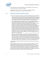
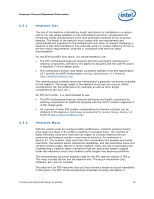
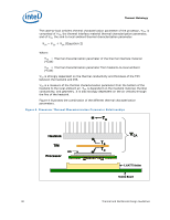
Processor Thermal/Mechanical Information 2.4 System Thermal Solution Considerations 2.4.1 Chassis Thermal Design Capabilities The Intel reference thermal solutions and Intel® Boxed Processor thermal solutions assume that the chassis delivers a maximum TA at the inlet of the processor fan heatsink. The following tables show the TA requirements for the reference solutions and Intel® Boxed Processor thermal solutions. Table 1. Heatsink Inlet Temperature of Intel Reference Thermal Solutions Type ATX D60188-001 ATX RCBFH3 ATX RCFH-4 BTX Type I Heatsink Inlet Temperature 40 °C 40 °C 39 °C 35.5 °C NOTE: 1. 2. Intel reference designs (D60188-001 and RCBFH-3) are assumed be used in the chassis where expected the temperature rise is 5 °C. Intel reference design (RCFH-4) is assumed be used in the thermally advantaged chassis and expected some of the temperature rise is induced by processor heat recirculation (refer to Thermally Advantaged Chassis version 1.1 for Thermally Advantaged Chassis thermal and mechanical requirements). Table 2. Heatsink Inlet Temperature of Intel® Boxed Processor thermal solutions Type Boxed Processor Heatsink for Intel® Core™2 Extreme quad-core processor QX6000 series at the 775_VR_CONFIG_05B, Intel® Core™2 Quad processor Q6000 series, Intel® Core™2 Extreme processor QX9000 series, and Intel® Core™2 Quad processor Q9000 and Q8000series Heatsink Inlet Temperature 39 °C NOTE: 1. Boxed Processor thermal solutions for ATX assume the use of the thermally advantaged chassis (refer to Thermally Advantaged Chassis version 1.1 for Thermally Advantaged Chassis thermal and mechanical requirements). 2.4.2 Improving Chassis Thermal Performance The heat generated by components within the chassis must be removed to provide an adequate operating environment for both the processor and other system components. Moving air through the chassis brings in air from the external ambient environment and transports the heat generated by the processor and other system components out of the system. The number, size and relative position of fans and vents determine the chassis thermal performance, and the resulting ambient temperature around the processor. The size and type (passive or active) of the thermal solution and the amount of system airflow can be traded off against each other to meet specific system design constraints. Additional constraints are board layout, spacing, component placement, acoustic requirements and structural considerations that limit the thermal solution size. For more information, refer to the Thermal and Mechanical Design Guidelines 27
-
 1
1 -
2
-
3
-
4
-
5
-
6
-
7
-
8
-
9
-
10
-
11
-
12
-
13
-
14
-
15
-
16
-
17
-
18
-
19
-
20
-
21
-
 22
22 -
 23
23 -
 24
24 -
 25
25 -
 26
26 -
 27
27 -
 28
28 -
 29
29 -
 30
30 -
 31
31 -
 32
32 -
33
-
34
-
35
-
36
-
37
-
38
-
39
-
40
-
41
-
42
-
43
-
44
-
45
-
46
-
47
-
48
-
49
-
50
-
51
-
52
-
53
-
54
-
55
-
56
-
57
-
58
-
59
-
60
-
61
-
62
-
63
-
64
-
65
-
66
-
67
-
68
-
69
-
70
-
71
-
72
-
73
-
74
-
75
-
76
-
77
-
78
-
79
-
80
-
81
-
82
-
83
-
84
-
85
-
86
-
87
-
88
-
89
-
90
-
91
-
92
-
93
-
94
-
95
-
96
-
97
-
98
-
99
-
100
-
101
-
102
-
103
-
104
-
105
-
106
-
107
-
108
-
109
-
110
-
111
-
112
-
113
-
114
-
115
-
116
-
117
-
118
-
119
-
120
-
121
-
122
-
123
-
124
 |
 |