Intel Q9450 Design Guidelines - Page 41
Digital Thermal Sensor
 |
UPC - 735858198493
View all Intel Q9450 manuals
Add to My Manuals
Save this manual to your list of manuals |
Page 41 highlights
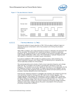
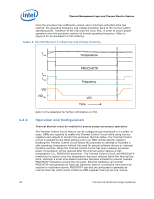
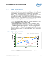
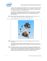
Thermal Management Logic and Thermal Monitor Feature 4.2.9 Digital Thermal Sensor Multiple digital thermal sensors can be implemented within the package without adding a pair of signal pins per sensor as required with the thermal diode. The digital thermal sensor is easier to place in thermally sensitive locations of the processor than the thermal diode. This is achieved due to a smaller foot print and decreased sensitivity to noise. Since the DTS is factory set on a per-part basis there is no need for the health monitor components to be updated at each processor family. The processor uses the Digital Thermal Sensor (DTS) as the on-die sensor to use for fan speed control (FSC). The DTS replaces the on-die thermal diode used in previous product. The DTS is monitoring the same sensor that activates the TCC (see Section 4.2.2). Readings from the DTS are relative to the activation of the TCC. The DTS value where TCC activation occurs is 0 (zero). A TCONTROL value will be provided for use with DTS. The usage model for TCONTROL with the DTS is the same as with the on-die thermal diode: If the Digital Thermometer is less than TCONTROL, the fan speed can be reduced. If the Digital Thermometer is greater than or equal to TCONTROL, then TC must be maintained at or below the Thermal Profile for the measured power dissipation. The calculation of TCONTROL is slightly different from previous product. There is no base value to sum with the TOFFSET located in the same MSR as used in previous processors. The BIOS only needs to read the TOFFSET MSR and provide this value to the fan speed control device. Figure 9. TCONTROL for Digital Thermometer Thermal Diode Temperature Digital Thermometer Temperature Tcontrol= 66 Tcontrol= -10 70 0 60 20 50 Temperature 30 40 Power 40 30 50 20 Fan Speed 60 10 70 Time Note: The processor does not have an on-die thermal diode. The TCONTROL in the MSR is relevant only to the DTS. Thermal and Mechanical Design Guidelines 41
-
 1
1 -
2
-
3
-
4
-
5
-
6
-
7
-
8
-
9
-
10
-
11
-
12
-
13
-
14
-
15
-
16
-
17
-
18
-
19
-
20
-
21
-
22
-
23
-
24
-
25
-
26
-
27
-
28
-
29
-
30
-
31
-
32
-
33
-
34
-
35
-
 36
36 -
 37
37 -
 38
38 -
 39
39 -
 40
40 -
 41
41 -
 42
42 -
 43
43 -
 44
44 -
 45
45 -
 46
46 -
47
-
48
-
49
-
50
-
51
-
52
-
53
-
54
-
55
-
56
-
57
-
58
-
59
-
60
-
61
-
62
-
63
-
64
-
65
-
66
-
67
-
68
-
69
-
70
-
71
-
72
-
73
-
74
-
75
-
76
-
77
-
78
-
79
-
80
-
81
-
82
-
83
-
84
-
85
-
86
-
87
-
88
-
89
-
90
-
91
-
92
-
93
-
94
-
95
-
96
-
97
-
98
-
99
-
100
-
101
-
102
-
103
-
104
-
105
-
106
-
107
-
108
-
109
-
110
-
111
-
112
-
113
-
114
-
115
-
116
-
117
-
118
-
119
-
120
-
121
-
122
-
123
-
124
 |
 |