Intel Q9450 Design Guidelines - Page 68
Heatsink Selection Guidelines
 |
UPC - 735858198493
View all Intel Q9450 manuals
Add to My Manuals
Save this manual to your list of manuals |
Page 68 highlights
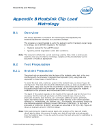
LGA775 Socket Heatsink Loading A.2.5.1 Motherboard Stiffening Considerations To protect LGA775 socket solder joint, designers need to drive their mechanical design to: Allow downward board deflection to put the socket balls in a desirable force state to protect against fatigue failure of socket solder joint (refer to Sections A.2.1, A.2.2, and A.2.3.) Prevent board upward bending during mechanical shock event Define load paths that keep the dynamic load applied to the package within specifications published in the processor datasheet Limiting board deflection may be appropriate in some situations like: Board bending during shock Board creep with high heatsink preload However, the load required to meet the board deflection recommendation (refer to Section A.2.3) with a very stiff board may lead to heatsink preloads exceeding package maximum load specification. For example, such a situation may occur when using a backing plate that is flush with the board in the socket area, and prevents the board to bend underneath the socket. A.3 Heatsink Selection Guidelines Evaluate carefully heatsinks coming with motherboard stiffening devices (like backing plates), and conduct board deflection assessments based on the board deflection metric. Solutions derived from the reference design comply with the reference heatsink preload, for example: The Boxed Processor The reference design (RCFH-4, RCBFH-3 and D60188-001) Intel will collaborate with vendors participating in its third party test house program to evaluate third party solutions. Vendor information is available in Intel® Core™2 Quad Processor Support Components webpage www.intel.com/go/thermal_Core2Quad. § 68 Thermal and Mechanical Design Guidelines
-
 1
1 -
2
-
3
-
4
-
5
-
6
-
7
-
8
-
9
-
10
-
11
-
12
-
13
-
14
-
15
-
16
-
17
-
18
-
19
-
20
-
21
-
22
-
23
-
24
-
25
-
26
-
27
-
28
-
29
-
30
-
31
-
32
-
33
-
34
-
35
-
36
-
37
-
38
-
39
-
40
-
41
-
42
-
43
-
44
-
45
-
46
-
47
-
48
-
49
-
50
-
51
-
52
-
53
-
54
-
55
-
56
-
57
-
58
-
59
-
60
-
61
-
62
-
 63
63 -
 64
64 -
 65
65 -
 66
66 -
 67
67 -
 68
68 -
 69
69 -
 70
70 -
 71
71 -
 72
72 -
 73
73 -
74
-
75
-
76
-
77
-
78
-
79
-
80
-
81
-
82
-
83
-
84
-
85
-
86
-
87
-
88
-
89
-
90
-
91
-
92
-
93
-
94
-
95
-
96
-
97
-
98
-
99
-
100
-
101
-
102
-
103
-
104
-
105
-
106
-
107
-
108
-
109
-
110
-
111
-
112
-
113
-
114
-
115
-
116
-
117
-
118
-
119
-
120
-
121
-
122
-
123
-
124
 |
 |
