Intel SBX44 User Guide - Page 64

on the heat sink., Remove the microprocessor
Page 64 highlights

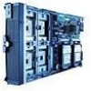
5. Remove the bezel assembly (see "Removing the blade server bezel assembly" on page 21 for instructions). 6. Identify the microprocessor to be removed. ✏ NOTE If you are replacing a failed microprocessor, verify that you have selected the correct microprocessor for replacement. ✏ NOTE The following procedure applies to the replacement or upgrade of microprocessors when using an existing heat sink. If using a new heat sink with pre-applied thermal interface (grease) material, follow the procedures outlined in "Installing a microprocessor" on page 26. 7. Remove the heat sink: a. Unscrew the captive screw (A) and lift the retention bar (B). b. Lift the heat sink (C) off of the microprocessor. c. The heat sink may be difficult to remove from the microprocessor due to the bond formed by the thermal grease. If necessary, use a slight twisting motion while simultaneously lifting up on the heat sink. A C B TP00371 8. Remove the microprocessor: a. Rotate the locking lever (A) on the microprocessor socket from its locked position until it stops or clicks. It should be in the fully extended 90-degree position. Attention: You must ensure that the locking lever on the microprocessor socket is in the fully open position before you remove the microprocessor from the socket. Failure to do so might result in permanent damage to the microprocessor, microprocessor socket, and/or system board. b. Lift the microprocessor (B) out of the socket. 52 Intel® Server Compute Blade SBX44: Installation and User's Guide

  • 1
  • 2
  • 3
  • 4
  • 5
  • 6
  • 7
  • 8
  • 9
  • 10
  • 11
  • 12
  • 13
  • 14
  • 15
  • 16
  • 17
  • 18
  • 19
  • 20
  • 21
  • 22
  • 23
  • 24
  • 25
  • 26
  • 27
  • 28
  • 29
  • 30
  • 31
  • 32
  • 33
  • 34
  • 35
  • 36
  • 37
  • 38
  • 39
  • 40
  • 41
  • 42
  • 43
  • 44
  • 45
  • 46
  • 47
  • 48
  • 49
  • 50
  • 51
  • 52
  • 53
  • 54
  • 55
  • 56
  • 57
  • 58
  • 59
  • 60
  • 61
  • 62
  • 63
  • 64
  • 65
  • 66
  • 67
  • 68
  • 69
  • 70
  • 71
  • 72
  • 73
  • 74
  • 75
  • 76
  • 77
  • 78
  • 79
  • 80
  • 81
  • 82
  • 83
  • 84
  • 85
  • 86
  • 87
  • 88
  • 89
  • 90
  • 91
  • 92

52
Intel® Server Compute Blade SBX44:
Installation and User’s Guide
5.
Remove the bezel assembly (see “Removing the blade server bezel assembly” on page 21 for
instructions).
6.
Identify the microprocessor to be removed.
NOTE
If you are replacing a failed microprocessor, verify that you have selected the correct
microprocessor for replacement.
NOTE
The following procedure applies to the replacement or upgrade of microprocessors when
using an existing heat sink. If using a new heat sink with pre-applied thermal interface
(grease) material, follow the procedures outlined in “Installing a microprocessor” on page
26.
7.
Remove the heat sink:
a.
Unscrew the captive screw (A) and lift the retention bar (B).
b.
Lift the heat sink (C) off of the microprocessor.
c.
The heat sink may be difficult to remove from the microprocessor due to the bond formed by
the thermal grease. If necessary, use a slight twisting motion while simultaneously lifting up
on the heat sink.
8.
Remove the microprocessor:
a.
Rotate the locking lever (A) on the microprocessor socket from its locked position until it
stops or clicks. It should be in the fully extended 90-degree position.
Attention:
You must ensure that the locking lever on the microprocessor socket is in the
fully open position before you remove the microprocessor from the socket. Failure to do so
might result in permanent damage to the microprocessor, microprocessor socket, and/or
system board.
b.
Lift the microprocessor (B) out of the socket.
TP00371
A
B
C