JVC VN-C625U Instructions - Page 9
Name and Function of Parts, POWER INPUT DC12V] DC12V Input Ter - video
 |
UPC - 046838018688
View all JVC VN-C625U manuals
Add to My Manuals
Save this manual to your list of manuals |
Page 9 highlights
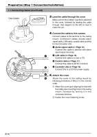
ENGLISH Name and Function of Parts ⅥCeiling Mount (Terminal Side) 9 8 1 7 6 2 5 3 4 1 Safety Wire 6 Locking Screw Hang this wire to the wire fastening hook & to Ensure to fasten the camera by fastening this prevent the camera from falling down. screw to the camera clamping bracket #. 2 [VIDEO OUT] Coaxial Cable Terminal 7 [ALARM IN/OUT] Alarm Input/Output Ter- Output terminal for composite video signals minals (1 Vp-p and output impedance of 75Ø). Con- Terminals for alarm input and output. nect this to devices such as video monitors. (☞ Page 15) (☞ Page 17) Pin No. Signal Name Output is restricted signals in the NTSC format only. 1 Alarm Output Alarm Output 1 2 Alarm Output 2 3 [POWER INPUT DC12V] DC12V Input Ter- minal 3 Alarm Input Alarm Input 1 4 Alarm Input 2 Connect this to the Converter Unit that has 5 been supplied. GND 4 Safety Wire Mounting Hole 8 Cover This is a protection cover. Cut a slit in the rub- To prevent the camera from falling down, attach a wire from the ceiling slab or channel to this hole. ber cap attached to the cover when wiring cables. (☞ Page 13) 5 [10BASE-T/100BASE-TX] 10BASE-T/ 100BASE-TX Terminal This is a 10BASE-T/100BASE-TX terminal. It is used for connecting to the network via LAN 9 Cover Fastening Screw This is used for fastening the cover 8 and ceiling mount. To remove cover 8, do so by unfastening this screw. cables. (☞ Page 16) E-9
-
 1
1 -
2
-
3
-
 4
4 -
 5
5 -
 6
6 -
 7
7 -
 8
8 -
 9
9 -
 10
10 -
 11
11 -
 12
12 -
 13
13 -
 14
14 -
15
-
16
-
17
-
18
-
19
-
20
-
21
-
22
-
23
-
24
-
25
-
26
-
27
-
28
-
29
-
30
-
31
-
32
-
33
-
34
-
35
-
36
-
37
-
38
-
39
-
40
-
41
-
42
-
43
-
44
-
45
-
46
-
47
-
48
-
49
-
50
-
51
-
52
-
53
-
54
-
55
-
56
-
57
-
58
-
59
-
60
-
61
-
62
-
63
-
64
-
65
-
66
-
67
-
68
-
69
-
70
-
71
-
72
-
73
-
74
-
75
-
76
-
77
-
78
-
79
-
80
-
81
-
82
-
83
-
84
-
85
-
86
-
87
-
88
-
89
-
90
-
91
-
92
-
93
-
94
-
95
-
96
-
97
-
98
-
99
-
100
-
101
-
102
-
103
-
104
-
105
-
106
-
107
-
108
-
109
-
110
-
111
-
112
-
113
-
114
-
115
-
116
-
117
-
118
-
119
-
120
-
121
-
122
-
123
-
124
-
125
-
126
-
127
-
128
-
129
-
130
-
131
-
132
-
133
-
134
-
135
-
136
-
137
-
138
-
139
-
140
-
141
-
142
-
143
-
144
-
145
-
146
-
147
-
148
-
149
-
150
-
151
-
152
-
153
-
154
-
155
-
156
-
157
-
158
-
159
-
160
-
161
-
162
-
163
-
164
-
165
-
166
-
167
-
168
-
169
-
170
-
171
-
172
-
173
-
174
-
175
-
176
-
177
-
178
-
179
-
180
-
181
-
182
-
183
-
184
-
185
-
186
-
187
 |
 |
