Kenwood TS-480HX Operation Manual - Page 23
Tx/ Rx Unit
 |
View all Kenwood TS-480HX manuals
Add to My Manuals
Save this manual to your list of manuals |
Page 23 highlights
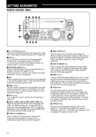
TX/ RX UNIT 3 GETTING ACQUAINTED qw e rt EXT.SP DATA REMOTE MIC PANEL i y COM PADDLE KEY u q MIC connector Connect a cable from the supplied microphone to this connector {page 6}. w PANEL connector Connect a cable from the Remote Control panel to this connector {page 6}. e EXT.SP jack Mate with a 3.5 mm (1/8"), 2-conductor (mono) plug for connecting an external speaker {page 7}. r DATA connector Mates with a 6-pin male DIN connector for connecting various accessory equipment, such as an external TNC/ MCP or a RTTY terminal {pages 77, 78}. t REMOTE connector Mates with a 6-pin male mini DIN connector for connecting an HF/ 50 MHz linear amplifier {page 77}. y COM connector Mates with a DB-9 female connector for connecting a computer via one of its serial communication (COM) ports {page 67}. Also used with the Quick Data Transfer function {pages 66, 76} and DX PacketCluster Tune function {pages 72, 79}. u PADDLE and KEY jacks The PADDLE jack mates with a 6.3 mm (1/4") 3-conductor plug for connecting a keyer paddle to the internal electronic keyer. The KEY jack mates with a 3.5 mm (1/8") 2-conductor plug for connecting an external key for CW operation. Refer to "Keys for CW (PANEL and KEY)" {page 7} before using these jacks. i Plastic cover If the EXT.SP jack, DATA connector and REMOTE connector are not used, attach this cover to protect the connectors from dust. 15
-
 1
1 -
2
-
3
-
4
-
5
-
6
-
7
-
8
-
9
-
10
-
11
-
12
-
13
-
14
-
15
-
16
-
17
-
 18
18 -
 19
19 -
 20
20 -
 21
21 -
 22
22 -
 23
23 -
 24
24 -
 25
25 -
 26
26 -
 27
27 -
 28
28 -
29
-
30
-
31
-
32
-
33
-
34
-
35
-
36
-
37
-
38
-
39
-
40
-
41
-
42
-
43
-
44
-
45
-
46
-
47
-
48
-
49
-
50
-
51
-
52
-
53
-
54
-
55
-
56
-
57
-
58
-
59
-
60
-
61
-
62
-
63
-
64
-
65
-
66
-
67
-
68
-
69
-
70
-
71
-
72
-
73
-
74
-
75
-
76
-
77
-
78
-
79
-
80
-
81
-
82
-
83
-
84
-
85
-
86
-
87
-
88
-
89
-
90
-
91
-
92
-
93
-
94
-
95
-
96
-
97
-
98
-
99
-
100
-
101
-
102
-
103
-
104
 |
 |
