Kenwood TS-480HX Operation Manual - Page 89
Installing Options
 |
View all Kenwood TS-480HX manuals
Add to My Manuals
Save this manual to your list of manuals |
Page 89 highlights
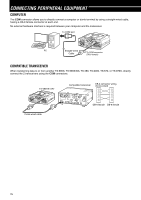
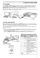
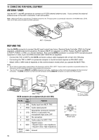
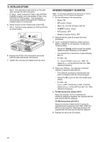
INSTALLING OPTIONS You will require a #1 Philips screwdriver to install the VGS-1. To install the YF-107 IF filter(s) and/ or SO-3 TCXO, you will also need a soldering iron (approx. 30 watts). REMOVING THE TOP COVER When installing the optional VGS-1, YF-107 IF filters or SO-3 TCXO, remove the top cover of the transceiver: 1 Remove the 8 screws. VGS-1 connector VGS-1 OPTTICOXNO MIC PANEL EXT.SP DATA REMOTE PADDLE KEY OPTIONOFPITLTIOENR2FILTER1 COM 5 Replace the shield cover and tighten the 4 screws. 6 Replace the top case (8 screws). Note: After the installation, you can adjust the VGS-1 playback volume by selecting Menu Nos. 14 and 15. YF-107C/ CN/ SN IF FILTERS AND SO-3 TCXO MIC PANEL EXT.SP DATA REMOTE PADDLE KEY OPTIOONPFTIILOTNERF2ILTER1 COM 2 Lift off the top cover. VGS-1 VOICE GUIDE & STORAGE UNIT SWITCH OFF THE POWER AND UNPLUG THE DC POWER CABLE BEFORE BEGINNING INSTALLATION. 1 Remove the top case (8 screws) {above}. 2 Loosen the 4 screws to remove the shield cover. VGS-1 connector OPTTICOXNO MIC PANEL EXT.SP DATA REMOTE PADDLE KEY OPTIONOFPITLTIOENR2FILTER1 COM 3 There are 5 rubber cushions in the VGS-1 package. Use the 2 rubber cushions shown below and attach them to the VGS-1. The remaining cushions are not used. 4 Plug the VGS-1 into the VGS-1 connector of the PC board, pressing down on the top of the VGS-1 until secure. SWITCH OFF THE POWER AND UNPLUG THE DC POWER CABLE BEFORE BEGINNING INSTALLATION. Three different types of IF filters (YF-107C, YF-107CN, and YF-107SN) are available for the TS-480 transceiver. You can install a maximum of 2 IF filters in the transceiver. Refer to page 90 for the bandwidth information on each filter. As for the SO-3 option improves the transceiver frequency stability to ±0.5 ppm. 1 Remove the top case (8 screws). 2 Locate the filter and TCXO PCB and loosen the 3 screws. IF filter/ TCXO PCB OPTTICOXNO OPTTICOXNO OPTTICOXNO OPTTICOXNO MIC PANEL EXT.SP DATA REMOTE PADDLE KEY OPTIOONPFTIILOTNERF2ILTER1 COM 3 Unlatch the connectors by pressing the connector tabs upwards. OPTIOONPFTILIOTENRF2ILTER1 MIC PANEL EXT.SP DATA REMOTE PADDLE KEY OPTIOONPFTIILOTNERF2ILTER1 COM 4 Insert the IF filter(s) and/ or SO-3 TCXO. Calibration hole Secondary IF filter SO-3 Primary IF filter OPTIOONPFTILIOTENRF2ILTER1 81
-
 1
1 -
2
-
3
-
4
-
5
-
6
-
7
-
8
-
9
-
10
-
11
-
12
-
13
-
14
-
15
-
16
-
17
-
18
-
19
-
20
-
21
-
22
-
23
-
24
-
25
-
26
-
27
-
28
-
29
-
30
-
31
-
32
-
33
-
34
-
35
-
36
-
37
-
38
-
39
-
40
-
41
-
42
-
43
-
44
-
45
-
46
-
47
-
48
-
49
-
50
-
51
-
52
-
53
-
54
-
55
-
56
-
57
-
58
-
59
-
60
-
61
-
62
-
63
-
64
-
65
-
66
-
67
-
68
-
69
-
70
-
71
-
72
-
73
-
74
-
75
-
76
-
77
-
78
-
79
-
80
-
81
-
82
-
83
-
 84
84 -
 85
85 -
 86
86 -
 87
87 -
 88
88 -
 89
89 -
 90
90 -
 91
91 -
 92
92 -
 93
93 -
 94
94 -
95
-
96
-
97
-
98
-
99
-
100
-
101
-
102
-
103
-
104
 |
 |
