Kenwood TS-480HX Operation Manual - Page 86
Antenna Tuner, Mcp And Tnc
 |
View all Kenwood TS-480HX manuals
Add to My Manuals
Save this manual to your list of manuals |
Page 86 highlights
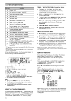
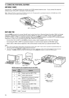
14 CONNECTING PERIPHERAL EQUIPMENT ANTENNA TUNER Use the ANT 1 and AT connectors to connect an AT-300 external antenna tuner. If you connect the external antenna tuner to the ANT 2 connector, it will not function. Note: When the AT-300 is used with the TS-480HX transceiver, the TX output power is automatically reduced to 100 W (AM mode: 25 W). Also, the AT-300 cannot be used for 50 MHz operation. 2 1 D13C.8V1 GND AT DC 2 13.8V ANT 1 connector MCP AND TNC Use the DATA connector to connect the AF input/ output lines from a Terminal Node Controller (TNC) for Packet operation, a Multimode Communications Processor (MCP) for operation on AFSK, Packet, PacTOR, AMTOR, G-TORTM, PSK31, or FAX, or a Clover interface. Also use the DATA connector to connect SSTV and phone patch equipment (1 male, 6-pin mini DIN connector (E57-0404-XX) is supplied). • Connect the TNC or MCP to the DATA connector using a cable equipped with a 6-pin mini DIN plug. • Connecting the TNC or MCP to a personal computer or dumb terminal requires an RS-232C cable. • Select LSB or USB mode (it depends on the communication mode) when you operate the MCP/ TNC. Note: ◆ Do not share a single power supply between the transceiver and the TNC or MCP. Keep as wide a separation as possible between the transceiver and the computer to reduce noise-pickup by the transceiver. ◆ The mini DIN connectors (REMOTE and DATA connectors) look alike. Confirm the number of pins before plugging into the transceiver connectors. The DATA connector is a 6-pin mini DIN connector and the REMOTE connector is an 8-pin mini DIN connector. Power Supply for MCP/ TNC MIC Mini DIN male PANEL EXT.SP DATA REMOTE (6-pin) COM PADELE KEY MCP/ TNC DATA connector pin assignment (6-pin mini DIN) Pin No. Pin Name Function 1 ANI Audio input from MCP/ TNC 2 ANG Audio signal ground Ground this terminal to transmit. 3 DTS When it is grounded, the microphone input turns OFF. 4 NC No connection 5 ANO Audio output for MCP/ TNC 6 Metal cover Squelch status SQC • Squelch open: Low impedance • Squelch close: High impedance GND Ground DC Power Supply for the transceiver DATA y t r e w q DATA connector (Front view) 78
-
 1
1 -
2
-
3
-
4
-
5
-
6
-
7
-
8
-
9
-
10
-
11
-
12
-
13
-
14
-
15
-
16
-
17
-
18
-
19
-
20
-
21
-
22
-
23
-
24
-
25
-
26
-
27
-
28
-
29
-
30
-
31
-
32
-
33
-
34
-
35
-
36
-
37
-
38
-
39
-
40
-
41
-
42
-
43
-
44
-
45
-
46
-
47
-
48
-
49
-
50
-
51
-
52
-
53
-
54
-
55
-
56
-
57
-
58
-
59
-
60
-
61
-
62
-
63
-
64
-
65
-
66
-
67
-
68
-
69
-
70
-
71
-
72
-
73
-
74
-
75
-
76
-
77
-
78
-
79
-
80
-
 81
81 -
 82
82 -
 83
83 -
 84
84 -
 85
85 -
 86
86 -
 87
87 -
 88
88 -
 89
89 -
 90
90 -
 91
91 -
92
-
93
-
94
-
95
-
96
-
97
-
98
-
99
-
100
-
101
-
102
-
103
-
104
 |
 |
