Kenwood TS-480HX Operation Manual - Page 85
Rtty Operation, Hf/ 50 Mhz Linear Amplifier
 |
View all Kenwood TS-480HX manuals
Add to My Manuals
Save this manual to your list of manuals |
Page 85 highlights
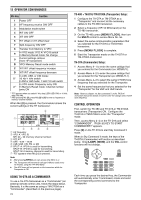
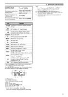
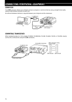
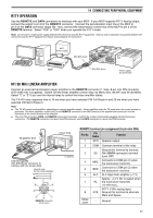
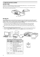
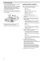
14 CONNECTING PERIPHERAL EQUIPMENT RTTY OPERATION Use the REMOTE and DATA connectors to interface with your MCP. If your MCP supports RTTY keying output, connect the output to pin 8 of the REMOTE connector. Connect the demodulation input line of the MCP to pin 5 of the DATA connector {page 78}. Also, connect the transmission control line of the MCP to pin 3 of the REMOTE terminal. Select "FSK" or "FSR" when you operate the RTTY mode. Note: Do not share a single power supply between the transceiver and the RTTY equipment. Keep as wide a separation as possible between the transceiver and the RTTY equipment to reduce noise-pickup by the transceiver. MCP Power supply EXT.SP DATA REMOTE MIC PANEL Mini-DIN (6-pin) COM PADELE KEY MCP Mini-DIN (8-pin) Power supply for the TS-480 HF/ 50 MHz LINEAR AMPLIFIER Connect an external transmission power amplifier to the REMOTE connector (1 male, 8-pin mini DIN connector (E57-0405-XX) is supplied). Switch ON the linear amplifier control relay via Menu Nos. 28 (HF) and 29 (50 MHz). Select "2" or "3" if you use the internal relay to control the linear amplifier status. The TX/ RX relay response time is 10 ms when you have selected CW Full Break-in and 25 ms when you have selected CW Semi Break-in. Note: ◆ The TX/ RX control method differs, depending on external amplifier models. Some amplifiers enter the TX mode when the control terminal is grounded. For those amplifiers, connect pin 2 of the REMOTE connector to the GND terminal of the amplifier and connect pin 4 of the connector to the control terminal of the amplifier. ◆ The mini DIN connectors (DATA and REMOTE connectors) look alike. Confirm the number of pins before plugging into the transceiver connectors. The REMOTE connector is an 8-pin mini DIN connector and the DATA connector is a 6-pin mini DIN connector. TS-480HX/ SAT Linear Amp. EXT.SP DATA REMOTE MIC PANEL PADELE KEY COM Use the supplied mini DIN (8-pin) connector to interface with the Linear Amp. Internal relay for the Linear amplifier. r w t u i y GND t e wr q REMOTE connector (Front view) To antenna REMOTE terminal pin assignment (8-pin mini DIN) Pin No. Pin Name Function 1 SPO Speaker output 2 COM Common terminal of the relay 3 4 5 6 7 8 Metal cover SS MKE BRK ALC RL RTK Ground this terminal to transmit. ANI (DATA connector) terminal turns OFF. Connects to COM (pin 2) when the transceiver transmits. Connects to COM (pin 2) when the transceiver receives. ALC input from amplifier (-7 V) Approx. +12 V DC is output when the transceiver transmits (10 mA max.). RTTY (FSK) keying input. Ground this terminal to alternate Mark and Space. - Ground 77
-
 1
1 -
2
-
3
-
4
-
5
-
6
-
7
-
8
-
9
-
10
-
11
-
12
-
13
-
14
-
15
-
16
-
17
-
18
-
19
-
20
-
21
-
22
-
23
-
24
-
25
-
26
-
27
-
28
-
29
-
30
-
31
-
32
-
33
-
34
-
35
-
36
-
37
-
38
-
39
-
40
-
41
-
42
-
43
-
44
-
45
-
46
-
47
-
48
-
49
-
50
-
51
-
52
-
53
-
54
-
55
-
56
-
57
-
58
-
59
-
60
-
61
-
62
-
63
-
64
-
65
-
66
-
67
-
68
-
69
-
70
-
71
-
72
-
73
-
74
-
75
-
76
-
77
-
78
-
79
-
 80
80 -
 81
81 -
 82
82 -
 83
83 -
 84
84 -
 85
85 -
 86
86 -
 87
87 -
 88
88 -
 89
89 -
 90
90 -
91
-
92
-
93
-
94
-
95
-
96
-
97
-
98
-
99
-
100
-
101
-
102
-
103
-
104
 |
 |
