Kenwood TS-480HX Operation Manual - Page 69
Attenuator, Auto Mode
 |
View all Kenwood TS-480HX manuals
Add to My Manuals
Save this manual to your list of manuals |
Page 69 highlights
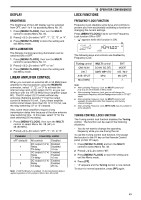
■ Presetting After each successful tuning session, the AT Preset memory function stores the position of the tuning capacitor in the memory. The position of the capacitor is stored for each of the antenna tuner bands (see the following table) and for each antenna connector (ANT 1 and ANT 2). Press [AT] momentarily. • "ATsT" will appear, showing that the antenna tuner is in-line (not bypassed). • Each time you go across the antenna tuner band, the AT Preset memory is automatically recalled to position the tuning capacitor without the need for retuning. If no preset data exists for a particular band/ antenna combination, then the default data of 50 Ω is used. Note: Tuning may restart in order to obtain the optimum matching condition even though the current antenna tuner band has the preset data. AT Preset Frequency Range (MHz) 0.03 ~ 1.85 2.50 ~ 3.525 3.575 ~ 3.725 4.10 ~ 6.90 7.03 ~ 7.10 7.50 ~ 10.50 14.10 ~ 14.50 18.50 ~ 21.15 21.50 ~ 25.50 29.00 ~ 30.00 51.00 ~ 52.00 53.00 ~ 60.00 1.85 ~ 2.50 3.525 ~ 3.575 3.725 ~ 4.10 6.90 ~ 7.03 7.10 ~ 7.50 10.50 ~ 14.10 14.50 ~ 18.50 21.15 ~ 21.50 25.50 ~ 29.00 30.00 ~ 51.00 52.00 ~ 53.00 ■ External Antenna Tuner type If you want to use the external antenna tuner, AT-300 with the TS-480 transceiver, access Menu No. 27 and confirm that "At1" is selected (default). "At2" is reserved for future updates. Note: When the AT-300 is used with the TS-480HX transceiver, TX power is automatically reduced to 100 W (AM mode: 25 W). Also, the AT-300 cannot be used for 50 MHz operation. ATTENUATOR The attenuator function is useful when extremely strong signals exist nearby your receiving frequency. When these type of signals exist nearby your receiving frequency, the AGC function may be erroneously controlled by the strong signals, rather than by the target receiving signal. If this happens, the target receiving signal can be masked and buried by the strong signals. In this case, turn the Attenuator function ON. When it is ON, the signal is attenuated approximately 12 dB. 1 Press [ATT/PRE/ ANT1/2] until the ATT icon appears on the display. • "ATT" appears when it is turned ON. 13 OPERATOR CONVENIENCES To return to normal operation, press [ATT/PRE/ ANT1/2] until both the ATT and the PRE icons disappear. AUTO MODE You can configure a maximum of 32 frequency borders (VFO A and B) to change the operating mode automatically as you change the VFO frequency. As a default, the following modes are programmed on each operating band. 0.03 MHz ~ 9.5 MHz: LSB 9.5 MHz ~ 60 MHz: USB To add the frequency borders to the Auto Mode selection: 1 Press and hold [MODE]+[ ] (POWER) to turn the transceiver ON. • "AUTOMODE" appears on the sub-display. 2 Select an Auto Mode frequency memory channel number by turning the MULTI control. Auto Memory channels 00 to 31 are available. 3 Turn the Tuning control to select a desired frequency border (or enter the frequency with the keypad {page 34}) to change the operating mode. 4 Press [MODE] or [MODE] (1 s) until the desired communication mode appears {page 19}. 5 Repeat steps 2 ~ 4 until you have added all the data. 6 Press [MTR/ CLR] to exit the Auto Mode frequency configuration. The table below shows the default Auto Mode frequency borders for the transceiver. When you access Menu No. 02 and select "on", "AUTO" appears. The transceiver automatically selects the mode; LSB for frequencies below 9.5 MHz and USB for frequencies greater than or equal to 9.5 MHz (default). Channel No. Data Operating mode 0 9.5 MHz LSB 1 9.5 MHz LSB 0.03 MHz 2 9.5 MHz LSB ≤ LSB < 9.5 MHz 3 9.5 MHz LSB 9.5 MHz ≤ USB ≤ • • 60.0 MHz • • 31 9.5 MHz LSB 61
-
 1
1 -
2
-
3
-
4
-
5
-
6
-
7
-
8
-
9
-
10
-
11
-
12
-
13
-
14
-
15
-
16
-
17
-
18
-
19
-
20
-
21
-
22
-
23
-
24
-
25
-
26
-
27
-
28
-
29
-
30
-
31
-
32
-
33
-
34
-
35
-
36
-
37
-
38
-
39
-
40
-
41
-
42
-
43
-
44
-
45
-
46
-
47
-
48
-
49
-
50
-
51
-
52
-
53
-
54
-
55
-
56
-
57
-
58
-
59
-
60
-
61
-
62
-
63
-
 64
64 -
 65
65 -
 66
66 -
 67
67 -
 68
68 -
 69
69 -
 70
70 -
 71
71 -
 72
72 -
 73
73 -
 74
74 -
75
-
76
-
77
-
78
-
79
-
80
-
81
-
82
-
83
-
84
-
85
-
86
-
87
-
88
-
89
-
90
-
91
-
92
-
93
-
94
-
95
-
96
-
97
-
98
-
99
-
100
-
101
-
102
-
103
-
104
 |
 |
