Konica Minolta bizhub C280 Service Manual - Page 52

Appendix

Page 52 highlights

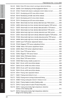
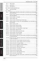
bizhub C360/C280/C220 OUTLINE MAINTENANCE TROUBLESHOOTING ADJUSTMENT / SETTING Field Service Ver. 1.0 Jul. 2009 22.3.28 Printer 4-color: white lines, white bands, colored lines and colored bands in main scan direction 717 22.3.29 Printer 4-color: uneven density in sub scan direction 718 22.3.30 Printer 4-color: uneven density in main scan direction 719 22.3.31 Printer 4-color: low image density 720 22.3.32 Printer 4-color: poor color reproduction 721 22.3.33 Printer 4-color: incorrect color image registration 722 22.3.34 Printer 4-color: void areas, white spots 724 22.3.35 Printer 4-color: colored spots 725 22.3.36 Printer 4-color: poor fusing performance, offset 726 22.3.37 Printer 4-color: brush effect, blurred image 727 22.3.38 Printer 4-color: back marking 728 22.3.39 Printer 4-color: uneven image 729 23. IC protector ...730 23.1 Outline ...730 23.2 IC protector list 730 23.2.1 Main body 730 23.2.2 DF-617 ...734 23.2.3 PC-107/PC-207 735 23.2.4 PC-408...736 23.2.5 JS-505...736 23.2.6 FS-527 ...737 23.2.7 SD-509...738 23.2.8 FS-529 ...739 APPENDIX 24. PARTS LAYOUT DRAWING 741 24.1 Main body ...741 24.1.1 Scanner section 741 24.1.2 Front side 742 24.1.3 Left side ...744 24.1.4 Back side 745 24.1.5 Right side 748 24.1.6 Manual bypass tray 749 24.1.7 Tray 1 ...750 24.1.8 Tray 2 ...751 24.1.9 Fusing/paper exit section 752 24.2 DF-617/SP-501 753 xxv APPENDIX

  • 1
  • 2
  • 3
  • 4
  • 5
  • 6
  • 7
  • 8
  • 9
  • 10
  • 11
  • 12
  • 13
  • 14
  • 15
  • 16
  • 17
  • 18
  • 19
  • 20
  • 21
  • 22
  • 23
  • 24
  • 25
  • 26
  • 27
  • 28
  • 29
  • 30
  • 31
  • 32
  • 33
  • 34
  • 35
  • 36
  • 37
  • 38
  • 39
  • 40
  • 41
  • 42
  • 43
  • 44
  • 45
  • 46
  • 47
  • 48
  • 49
  • 50
  • 51
  • 52
  • 53
  • 54
  • 55
  • 56
  • 57
  • 58
  • 59
  • 60
  • 61
  • 62
  • 63
  • 64
  • 65
  • 66
  • 67
  • 68
  • 69
  • 70
  • 71
  • 72
  • 73
  • 74
  • 75
  • 76
  • 77
  • 78
  • 79
  • 80
  • 81
  • 82
  • 83
  • 84
  • 85
  • 86
  • 87
  • 88
  • 89
  • 90
  • 91
  • 92
  • 93
  • 94
  • 95
  • 96
  • 97
  • 98
  • 99
  • 100
  • 101
  • 102
  • 103
  • 104
  • 105
  • 106
  • 107
  • 108
  • 109
  • 110
  • 111
  • 112
  • 113
  • 114

bizhub C360/C280/C220
OUTLINE
MAINTENANCE
ADJUSTMENT / SETTING
TROUBLESHOOTING
APPENDIX
Field Service
V
er. 1.0 Jul. 2009
xxv
22.3.28
Printer 4-color: white lines, white bands, colored lines and colored bands in
main scan direction
...................................................................................
717
22.3.29
Printer 4-color: uneven density in sub scan direction
................................
718
22.3.30
Printer 4-color: uneven density in main scan direction
..............................
719
22.3.31
Printer 4-color: low image density
.............................................................
720
22.3.32
Printer 4-color: poor color reproduction
....................................................
721
22.3.33
Printer 4-color: incorrect color image registration
.....................................
722
22.3.34
Printer 4-color: void areas, white spots
.....................................................
724
22.3.35
Printer 4-color: colored spots
....................................................................
725
22.3.36
Printer 4-color: poor fusing performance, offset
........................................
726
22.3.37
Printer 4-color: brush effect, blurred image
...............................................
727
22.3.38
Printer 4-color: back marking
....................................................................
728
22.3.39
Printer 4-color: uneven image
...................................................................
729
23.
IC protector
.........................................................................................................
730
23.1
Outline
..............................................................................................................
730
23.2
IC protector list
..................................................................................................
730
23.2.1
Main body
.................................................................................................
730
23.2.2
DF-617
......................................................................................................
734
23.2.3
PC-107/PC-207
.........................................................................................
735
23.2.4
PC-408
......................................................................................................
736
23.2.5
JS-505
.......................................................................................................
736
23.2.6
FS-527
......................................................................................................
737
23.2.7
SD-509
......................................................................................................
738
23.2.8
FS-529
......................................................................................................
739
APPENDIX
24.
PARTS LAYOUT DRAWING
................................................................................
741
24.1
Main body
.........................................................................................................
741
24.1.1
Scanner section
........................................................................................
741
24.1.2
Front side
..................................................................................................
742
24.1.3
Left side
....................................................................................................
744
24.1.4
Back side
...................................................................................................
745
24.1.5
Right side
..................................................................................................
748
24.1.6
Manual bypass tray
...................................................................................
749
24.1.7
Tray 1
........................................................................................................
750
24.1.8
Tray 2
........................................................................................................
751
24.1.9
Fusing/paper exit section
..........................................................................
752
24.2
DF-617/SP-501
.................................................................................................
753